Share with friends:

Gasoline car engine Renault Fluence 1

General information
This book covers 1.4L petrol engines (H4J), 1.6 l (K4M) and 2.0 l (M4R). Valve clearance adjustment is automatic using hydraulic tappets and does not require manual adjustment. The water pump is driven by a V-belt or...
This book covers 1.4L petrol engines (H4J), 1.6 l (K4M) and 2.0 l (M4R). Valve clearance adjustment is automatic using hydraulic tappets and does not require manual adjustment. The water pump is driven by a V-belt or...

Engine identification data
M4R engine identification data located on the cylinder block (A) and on the timing cover (IN). Identification data for K-series engines located on the cylinder block (1). The quality class is indicated on the bolt at...
M4R engine identification data located on the cylinder block (A) and on the timing cover (IN). Identification data for K-series engines located on the cylinder block (1). The quality class is indicated on the bolt at...

Bolt tightening methods
As a rule, when repairing cars, two methods of controlled tightening are used: this is tightening with the required torque and tightening at a given angle (also called torque and angle tightening). Torque tightening The...
As a rule, when repairing cars, two methods of controlled tightening are used: this is tightening with the required torque and tightening at a given angle (also called torque and angle tightening). Torque tightening The...

Safety precautions when performing internal combustion engine repairs
To ensure a quality repair: use recommended professional repair materials and original spare parts; observe tightening torques; follow the instructions for parts requiring mandatory replacement after removal,...
To ensure a quality repair: use recommended professional repair materials and original spare parts; observe tightening torques; follow the instructions for parts requiring mandatory replacement after removal,...
Aggregate replacement (new engine)
Parts to be removed from a used engine and installed on a new engine (provided they are correct): all hoses of the engine cooling system; oil pressure sensor; knock sensor; intake manifold; an exhaust manifold;...
Parts to be removed from a used engine and installed on a new engine (provided they are correct): all hoses of the engine cooling system; oil pressure sensor; knock sensor; intake manifold; an exhaust manifold;...
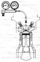
Cylinder Leak Check
Note. Checking cylinders for leaks can be done as an alternative to measuring compression. Using this method, you can measure the total amount of leakage from the engine cylinders and determine its location. A similar...
Note. Checking cylinders for leaks can be done as an alternative to measuring compression. Using this method, you can measure the total amount of leakage from the engine cylinders and determine its location. A similar...

Compression test
Remove the engine top cover, coils and spark plugs (see corresponding operation). Connect a compression gauge to cylinder #1. Run the following commands using the scan tool: RZ003: «ADAPTATIFS MOTEUR»; VP036:...
Remove the engine top cover, coils and spark plugs (see corresponding operation). Connect a compression gauge to cylinder #1. Run the following commands using the scan tool: RZ003: «ADAPTATIFS MOTEUR»; VP036:...

Auxiliary equipment drive belt (K4M engine)
Attention. Do not turn the engine crankshaft in the opposite direction of rotation. Attention. Be sure to replace the accessory drive belt. Removing Place the car on a lift. Disconnect the battery. Remove the engine top...
Attention. Do not turn the engine crankshaft in the opposite direction of rotation. Attention. Be sure to replace the accessory drive belt. Removing Place the car on a lift. Disconnect the battery. Remove the engine top...

Auxiliary equipment drive belt (M4R engine)
Removing Place the car on a lift. Remove: right front wheel; right front fender (see corresponding operation); protective screen. Turn the accessory drive belt tensioner clockwise with a 14mm wrench. Lock the tension...
Removing Place the car on a lift. Remove: right front wheel; right front fender (see corresponding operation); protective screen. Turn the accessory drive belt tensioner clockwise with a 14mm wrench. Lock the tension...

Lower jet thrust (M4R engine)
Removing Install the car lift. Remove: engine crankcase mounting bolts; protective screen. Remove: fastening bots (1) anti-skid rods; anti-skid traction (2); bolt (3) fixing the lower jet thrust on the subframe; lower...
Removing Install the car lift. Remove: engine crankcase mounting bolts; protective screen. Remove: fastening bots (1) anti-skid rods; anti-skid traction (2); bolt (3) fixing the lower jet thrust on the subframe; lower...

Right pendulum suspension (M4R engine)
Removing Remove: engine crankcase mounting bolts; engine undertray protection; lower jet thrust. Disconnect the fuel feed line from the engine swing arm mount. Disconnect the fuel supply line (1) from the fuel rail....
Removing Remove: engine crankcase mounting bolts; engine undertray protection; lower jet thrust. Disconnect the fuel feed line from the engine swing arm mount. Disconnect the fuel supply line (1) from the fuel rail....

Left pendulum suspension (M4R engine)
Removing Place the car on a lift. Remove: left front wheel; left front fender liner; battery; battery shelf; air filter housing; engine undertray protection; lower jet thrust. Establish a support for removal and...
Removing Place the car on a lift. Remove: left front wheel; left front fender liner; battery; battery shelf; air filter housing; engine undertray protection; lower jet thrust. Establish a support for removal and...

Lower jet thrust (K4M engine)
Removing Place the car on a lift. Remove the engine crankcase mounting bolts and the protective screen. Remove: bolt (1) fastening the lower jet thrust to the front suspension subframe, lower tie rod bracket bolt to...
Removing Place the car on a lift. Remove the engine crankcase mounting bolts and the protective screen. Remove: bolt (1) fastening the lower jet thrust to the front suspension subframe, lower tie rod bracket bolt to...

Right pendulum suspension (K4M engine)
Removing Place the car on a lift. Remove: top cover of the engine; engine crankcase mounting bolts; engine undertray protection; lower jet thrust. Install fixture (replaces tool Mot. 1367), consisting of devices for...
Removing Place the car on a lift. Remove: top cover of the engine; engine crankcase mounting bolts; engine undertray protection; lower jet thrust. Install fixture (replaces tool Mot. 1367), consisting of devices for...

Left pendulum suspension (K4M engine)
Removing Place the car on a lift. Remove: top cover of the engine; battery; battery shelf; air filter housing; lower jet thrust. Install the battery harness groove (1). Move aside the battery harness groove. Disconnect...
Removing Place the car on a lift. Remove: top cover of the engine; battery; battery shelf; air filter housing; lower jet thrust. Install the battery harness groove (1). Move aside the battery harness groove. Disconnect...

Wiring harnesses
K4M engine The R37 connector of the circuit between the engine harness and the injection harness is shown in the figure. Switch off the ignition. Disconnect the battery. Disconnect the R37 connector of the circuit...
K4M engine The R37 connector of the circuit between the engine harness and the injection harness is shown in the figure. Switch off the ignition. Disconnect the battery. Disconnect the R37 connector of the circuit...

Wiring and connectors
K4M engine Disconnect connectors: block of wires from the air temperature sensor (12); wiring harnesses for ignition coils (13); knock sensor (14); oil pressure sensor (15); air conditioning compressor (16);...
K4M engine Disconnect connectors: block of wires from the air temperature sensor (12); wiring harnesses for ignition coils (13); knock sensor (14); oil pressure sensor (15); air conditioning compressor (16);...

Timing belt (K4M engine)
Tightening torques when removing and installing the timing belt Attention. Together with the belt, be sure to replace the tension and bypass rollers. Note. The method for removing and installing the timing belt for...
Tightening torques when removing and installing the timing belt Attention. Together with the belt, be sure to replace the tension and bypass rollers. Note. The method for removing and installing the timing belt for...

Timing chain (H4J engine)
Remove the engine complete with gearbox. Install the engine on a stand for assembly and disassembly. Drain the engine oil. Loosen the bolts (1) water pump pulley by blocking the water pump pulley with a screwdriver....
Remove the engine complete with gearbox. Install the engine on a stand for assembly and disassembly. Drain the engine oil. Loosen the bolts (1) water pump pulley by blocking the water pump pulley with a screwdriver....

Timing chain (M4R engine)
Tightening torques when removing and installing the timing chain Removing Remove the engine complete with gearbox. Install the engine on a stand for assembly and disassembly. Drain the engine oil. Remove the accessory...
Tightening torques when removing and installing the timing chain Removing Remove the engine complete with gearbox. Install the engine on a stand for assembly and disassembly. Drain the engine oil. Remove the accessory...
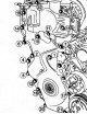
K4M engine cylinder head gasket
Place the car on a two post lift. Disconnect the battery. Remove the battery. Remove the engine top covers. Remove the engine undertray. Remove the accessory drive belt. Remove the timing belt. Remove the front bumper....
Place the car on a two post lift. Disconnect the battery. Remove the battery. Remove the engine top covers. Remove the engine undertray. Remove the accessory drive belt. Remove the timing belt. Remove the front bumper....
Cleaning the cylinder head of the K4M engine
Clean mating surfaces with DECAPJOINT (or similar) for removing gasket residue from mating surfaces of the oil pan and cylinder block. After applying the composition to the surface to be cleaned, wait about ten minutes,...
Clean mating surfaces with DECAPJOINT (or similar) for removing gasket residue from mating surfaces of the oil pan and cylinder block. After applying the composition to the surface to be cleaned, wait about ten minutes,...
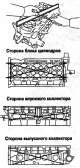
Checking the mating surface of the cylinder head of the K4M engine
Use a feeler gauge to check the flatness of the cylinder head mating surface. The maximum allowable flatness: no more than 0.05 mm. Attention. Grinding of the cylinder head is not permitted. Valve spring plunger...
Use a feeler gauge to check the flatness of the cylinder head mating surface. The maximum allowable flatness: no more than 0.05 mm. Attention. Grinding of the cylinder head is not permitted. Valve spring plunger...
Removing the valve springs of the K4M engine
To properly compress the valve springs, the tool plunger must be centered (Mot. 1502) along the valve stem. The valve spring plate must fit into the bore of the pressure sleeve of the tool (Mot. 1502). Remove: crackers;...
To properly compress the valve springs, the tool plunger must be centered (Mot. 1502) along the valve stem. The valve spring plate must fit into the bore of the pressure sleeve of the tool (Mot. 1502). Remove: crackers;...

Checking the height and tightness of the cylinder head of the K4M engine
Checking the height of the cylinder head Measure the height of the cylinder head. The height of the cylinder head is 137 mm. Check of tightness of a head of the block of cylinders Check the cylinder head for cracks...
Checking the height of the cylinder head Measure the height of the cylinder head. The height of the cylinder head is 137 mm. Check of tightness of a head of the block of cylinders Check the cylinder head for cracks...

Checking the diameters of the bearing journals and the holes of the bearings of the camshafts of the K4M engine
Measure the diameter of the camshafts. Camshaft journal diameter: necks No. 1, 2, 3, 4, 5 - 24.97925 mm; neck No. 6 - 27.979 - 28 mm. Measure the diameter of each hole in the camshaft bearings. Camshaft bearing bore...
Measure the diameter of the camshafts. Camshaft journal diameter: necks No. 1, 2, 3, 4, 5 - 24.97925 mm; neck No. 6 - 27.979 - 28 mm. Measure the diameter of each hole in the camshaft bearings. Camshaft bearing bore...

Checking the axial movement of the camshafts of the K4M engine
Install the camshafts, making sure they are in the correct position, and the cylinder head cover. Tighten in the order shown in the figure to the required torque: cylinder head bolts 13 -20-22-23 (8 Nm), cylinder head...
Install the camshafts, making sure they are in the correct position, and the cylinder head cover. Tighten in the order shown in the figure to the required torque: cylinder head bolts 13 -20-22-23 (8 Nm), cylinder head...

Checking the valves of the K4M engine
The diameter D of the valve stem is measured at distance X1. Inlet valves X1: = 75.14±0.35 mm, D = 5, 470 - 5.485 mm. Exhaust valves X1: = 77.5±0.35 mm, D = 5, 456 - 5.471 mm. Valve Test Diagram Valve head diameter D:...
The diameter D of the valve stem is measured at distance X1. Inlet valves X1: = 75.14±0.35 mm, D = 5, 470 - 5.485 mm. Exhaust valves X1: = 77.5±0.35 mm, D = 5, 456 - 5.471 mm. Valve Test Diagram Valve head diameter D:...

Checking the gap between the rods and the valve guides of the K4M engine
There are two ways to check the clearance between the valve stem and the valve guide. First way. Raise the valve head by 25 mm, then measure the movement of the valve in the direction of the arrows at an angle of 90°to...
There are two ways to check the clearance between the valve stem and the valve guide. First way. Raise the valve head by 25 mm, then measure the movement of the valve in the direction of the arrows at an angle of 90°to...

Checking the valve springs of the K4M engine
Check the deflection of the spring from the vertical, which should not exceed 1.2 mm. Check spring calibration. Spring length under load: under a load of 18 - 20 N, the length of the spring is 34.50 mm; under a load of...
Check the deflection of the spring from the vertical, which should not exceed 1.2 mm. Check spring calibration. Spring length under load: under a load of 18 - 20 N, the length of the spring is 34.50 mm; under a load of...

Assembling the MCC of the K4M engine
Insert the valve into the cylinder head. Put on the tip of the tool (Mot. 1511) on the valve stem (the inner diameter of the tip must be equal to the diameter of the rod). Keep the valve pressed against the seat. Spring...
Insert the valve into the cylinder head. Put on the tip of the tool (Mot. 1511) on the valve stem (the inner diameter of the tip must be equal to the diameter of the rod). Keep the valve pressed against the seat. Spring...

Cylinder block and crankshaft of the K4M engine
Install the flywheel retainer (Mot. 582-01 or Mot. 1677). Remove the cover and clutch disc. Remove flywheel. Remove the engine oil pan. Remove the timing belt tensioner pulley. Remove the water pump. Remove the engine...
Install the flywheel retainer (Mot. 582-01 or Mot. 1677). Remove the cover and clutch disc. Remove flywheel. Remove the engine oil pan. Remove the timing belt tensioner pulley. Remove the water pump. Remove the engine...

Cleaning the bottom of the K4M engine
Clear: cylinder block; crankshaft; engine tray; front cover of the engine block; crankshaft bearing caps.
Clear: cylinder block; crankshaft; engine tray; front cover of the engine block; crankshaft bearing caps.

Checking the mating plane of the cylinder block of the K4M engine
Check with a straightedge and a set of feeler gauges for the flatness of the mating plane of the cylinder block, which should not exceed 0.03 mm.
Check with a straightedge and a set of feeler gauges for the flatness of the mating plane of the cylinder block, which should not exceed 0.03 mm.
Checking the diameter of the main bearings of the crankshaft of the K4M engine
Install the crankshaft main bearing caps by installing cap 1 on the flywheel side. Tighten in the order shown in the figure to the required torque (25 Nm + 47°± 5°) and tighten the crankshaft main bearing cap bolts to...
Install the crankshaft main bearing caps by installing cap 1 on the flywheel side. Tighten in the order shown in the figure to the required torque (25 Nm + 47°± 5°) and tighten the crankshaft main bearing cap bolts to...

Checking the diameters of the main and connecting rod journals of the K4M engine
Checking the diameter of the main journals Check the diameter of the main journals. The diameter of the main journals should be within 47.990-48.010 mm. The procedure for tightening the bolts of the crankshaft main...
Checking the diameter of the main journals Check the diameter of the main journals. The diameter of the main journals should be within 47.990-48.010 mm. The procedure for tightening the bolts of the crankshaft main...

Removing the piston pins of the K4M engine
Remove the piston rings with piston ring pliers. Install the piston assembly with the connecting rod on the tool prism (Mot. 574-22). Align the piston pin with its exit hole in the prism (1). Using a press, press out...
Remove the piston rings with piston ring pliers. Install the piston assembly with the connecting rod on the tool prism (Mot. 574-22). Align the piston pin with its exit hole in the prism (1). Using a press, press out...

Checking the gap between the piston rings and the grooves of the K4M engine piston
Use a feeler gauge to check the clearances between the piston grooves and the piston rings. Checking the clearance between piston grooves and piston rings: 1 - probes; And - the wrong position of the probe; B - the...
Use a feeler gauge to check the clearances between the piston grooves and the piston rings. Checking the clearance between piston grooves and piston rings: 1 - probes; And - the wrong position of the probe; B - the...

Checking the gaps in the lock of the piston rings of the K4M engine
Install the piston ring in the cylinder. Move the piston ring to the middle of the cylinder with the piston. Measure the ring gap in the lock with a set of feeler gauges. Checking clearances in the piston ring lock: 1 -...
Install the piston ring in the cylinder. Move the piston ring to the middle of the cylinder with the piston. Measure the ring gap in the lock with a set of feeler gauges. Checking clearances in the piston ring lock: 1 -...

Installation of cylinder nozzles and cooling of the piston bottom of the K4M engine
Installation of nozzles for cooling the piston crown Install the tool plate on the cylinder block (2) (Mot. 1494), without tightening the two mounting bolts. Install the jig into the plate (the end of the conductor must...
Installation of nozzles for cooling the piston crown Install the tool plate on the cylinder block (2) (Mot. 1494), without tightening the two mounting bolts. Install the jig into the plate (the end of the conductor must...

Installation direction of the main bearing shells of the crankshaft of the K4M engine
Establish liners with flutes in all beds of the block of cylinders. Install the grooved shells in the main bearing caps 2 and 4, and the non-grooved shells in the main bearing caps 1,3 and 5.
Establish liners with flutes in all beds of the block of cylinders. Install the grooved shells in the main bearing caps 2 and 4, and the non-grooved shells in the main bearing caps 1,3 and 5.

Installing the shells of the main bearings of the K4M engine
Installing the main bearing shells in the bed of the cylinder block Install the fixture on the block (Mot. 1493-01). Press the special tool until the insert contacts the tool plate. Installing shells in main bearing...
Installing the main bearing shells in the bed of the cylinder block Install the fixture on the block (Mot. 1493-01). Press the special tool until the insert contacts the tool plate. Installing shells in main bearing...

Checking the diametrical clearance with the main journals of the crankshaft and bearings of the K4M engine
Note. When checking the clearance, never turn the crankshaft. Remove oil residues from the main journals and bearings of the cylinder block. Install the crankshaft and crankshaft thrust washers on the 3rd support...
Note. When checking the clearance, never turn the crankshaft. Remove oil residues from the main journals and bearings of the cylinder block. Install the crankshaft and crankshaft thrust washers on the 3rd support...

Checking the axial movement of the crankshaft of the K4M engine
Install the crankshaft. Check the presence of thrust half rings on the 3rd support (the grooves of the half rings must face the cheeks of the crankshaft). Note. The mating surfaces of the cylinder block and main bearing...
Install the crankshaft. Check the presence of thrust half rings on the 3rd support (the grooves of the half rings must face the cheeks of the crankshaft). Note. The mating surfaces of the cylinder block and main bearing...

Installing the connecting rod bearing shells of the K4M engine
The engine is equipped with liners without a mustache. Inserts are installed with a tool (Mot. 1492). Select the liner holder according to the engine model (engine model is indicated on the bracket). Install the insert...
The engine is equipped with liners without a mustache. Inserts are installed with a tool (Mot. 1492). Select the liner holder according to the engine model (engine model is indicated on the bracket). Install the insert...

Assembly of connecting rods with pistons of the K4M engine
The piston pins are installed with an interference fit in the upper heads of the connecting rods and rotate freely in the piston bosses. use kit (Mot. 574-22) and fixture (Mot. 574-24). Visually check: condition of...
The piston pins are installed with an interference fit in the upper heads of the connecting rods and rotate freely in the piston bosses. use kit (Mot. 574-22) and fixture (Mot. 574-24). Visually check: condition of...

Preparing the piston pins of the K4M engine
Check that the piston pins rotate freely in the bosses of the corresponding new pistons. Use centering mandrel C 13 and mounting mandrel A13 from the kit (Mot. 574-22) for piston pins without collar. Use centering...
Check that the piston pins rotate freely in the bosses of the corresponding new pistons. Use centering mandrel C 13 and mounting mandrel A13 from the kit (Mot. 574-22) for piston pins without collar. Use centering...

Setting the position of the pistons in relation to the connecting rods of the K4M engine
Pistons are labeled «V» on the head, which should be located on the side of the flywheel. Position the piston head with the mark «V» (1) up. Guide the connecting rod retainer (2) down.
Pistons are labeled «V» on the head, which should be located on the side of the flywheel. Position the piston head with the mark «V» (1) up. Guide the connecting rod retainer (2) down.

Assembling the piston and connecting rod of the K4M engine
Install ring B10 on the prism (1) and a piston supported by a ring (oriented in the correct position) and fasten all parts with a clamp (2). Make sure the piston pin bore is aligned with the B10 ring bore. Lubricate the...
Install ring B10 on the prism (1) and a piston supported by a ring (oriented in the correct position) and fasten all parts with a clamp (2). Make sure the piston pin bore is aligned with the B10 ring bore. Lubricate the...
Installation of piston rings of the K4M engine
The piston rings are matched to the piston and must move freely in the piston grooves. Observe the installation direction of the rings (TOP label is directed upwards). Observe the position of the lock of each ring.
The piston rings are matched to the piston and must move freely in the piston grooves. Observe the installation direction of the rings (TOP label is directed upwards). Observe the position of the lock of each ring.

Assembly of the lower part of the K4M engine
Lubricate the upper parts of the cylinders and the connecting rod journals of the crankshaft with engine oil. Reinstall the pistons and connecting rods with the tool. Install the crankshaft connecting rods. Install the...
Lubricate the upper parts of the cylinders and the connecting rod journals of the crankshaft with engine oil. Reinstall the pistons and connecting rods with the tool. Install the crankshaft connecting rods. Install the...

Installing the crankshaft oil seals of the K4M engine
Press in the crankshaft rear oil seal with a mandrel (Mot. 1129-01). Press in the front crankshaft oil seal with a mandrel (Mot. 1385). Install the flywheel with new mounting bolts. Install the flywheel retainer (Mot....
Press in the crankshaft rear oil seal with a mandrel (Mot. 1129-01). Press in the front crankshaft oil seal with a mandrel (Mot. 1385). Install the flywheel with new mounting bolts. Install the flywheel retainer (Mot....

Installing the cylinder head gasket for the K4M engine
Install a new cylinder head gasket. Install the cylinder head. Tighten the cylinder head bolts. Refill hydraulic tappets as working fluid from the pushers may leak if they are not operated for a long time. To make sure...
Install a new cylinder head gasket. Install the cylinder head. Tighten the cylinder head bolts. Refill hydraulic tappets as working fluid from the pushers may leak if they are not operated for a long time. To make sure...

K4M Engine Tightening Procedure
Tighten in order to the correct torque: bolts of fastening 22, 23, 20, 13 of a cover of a head of the block of cylinders (80 Nm); bolts 1-12, 14-19, 21-24 of fastening of a cover of a head of cylinders (120 Nm). Loosen...
Tighten in order to the correct torque: bolts of fastening 22, 23, 20, 13 of a cover of a head of the block of cylinders (80 Nm); bolts 1-12, 14-19, 21-24 of fastening of a cover of a head of cylinders (120 Nm). Loosen...

Replacing the camshaft seals of the K4M engine
Elastic camshaft seals are used in two versions, the seal in the first version has a spring (1) and V-shaped working edge (2). In the second variant, the stuffing box has a flat working edge (1) and safety sleeve (2),...
Elastic camshaft seals are used in two versions, the seal in the first version has a spring (1) and V-shaped working edge (2). In the second variant, the stuffing box has a flat working edge (1) and safety sleeve (2),...

Installing the camshaft seals for the intake and exhaust valves of the K4M engine
Installing the intake camshaft seals of the first version Install seals with tool (Mot. 1491) (1) and old nuts (2). Installing the exhaust camshaft seal Attention. Be sure to hold the seal by the protective sleeve (1),...
Installing the intake camshaft seals of the first version Install seals with tool (Mot. 1491) (1) and old nuts (2). Installing the exhaust camshaft seal Attention. Be sure to hold the seal by the protective sleeve (1),...

Main head cover for H4J, M4R engines
Remove: intake air duct; ignition coils; spark plug. Remove: fastening bolt (1) holder for connectors of the wiring harness of ignition and injection systems; holder (2) wiring harness connectors for ignition and...
Remove: intake air duct; ignition coils; spark plug. Remove: fastening bolt (1) holder for connectors of the wiring harness of ignition and injection systems; holder (2) wiring harness connectors for ignition and...

Timing pulleys for H4J and M4R engines
Remove the exhaust camshaft gear (3) with a flat wrench and a ratchet. Remove the intake camshaft dephaser (4) with a flat wrench and a ratchet. Replace: bolt of fastening of a gear pulley of a camshaft of final valves;...
Remove the exhaust camshaft gear (3) with a flat wrench and a ratchet. Remove the intake camshaft dephaser (4) with a flat wrench and a ratchet. Replace: bolt of fastening of a gear pulley of a camshaft of final valves;...

Camshafts for H4J and M4R engines
Turn away bolts of fastening of a case of camshafts. Detach the camshaft housing using a crankcase separator with silicone seals (Mot. 1716) (3). Remove the crankcase distribution rooms (4). Remove camshafts (5) and...
Turn away bolts of fastening of a case of camshafts. Detach the camshaft housing using a crankcase separator with silicone seals (Mot. 1716) (3). Remove the crankcase distribution rooms (4). Remove camshafts (5) and...

Checking the camshafts of the H4J and M4R engines
Clean the camshafts with a cleaner and dry them with a compressed air blow gun. Check that the surfaces of the camshafts are free of scratches, impact marks and excessive wear (replace the camshaft if necessary). The...
Clean the camshafts with a cleaner and dry them with a compressed air blow gun. Check that the surfaces of the camshafts are free of scratches, impact marks and excessive wear (replace the camshaft if necessary). The...

Camshaft color coding for H4J and M4R engines
H4J engine: bearing journal No. 1: 27.04 - 27.06 mm, bearing neck No. 2, 3, 4 and 5: 24.95 -24.97 mm. Place the camshaft on two lightly oiled v-blocks. Using a micrometer, measure the height of the cams (H). M4R engine:...
H4J engine: bearing journal No. 1: 27.04 - 27.06 mm, bearing neck No. 2, 3, 4 and 5: 24.95 -24.97 mm. Place the camshaft on two lightly oiled v-blocks. Using a micrometer, measure the height of the cams (H). M4R engine:...

Valvetrain for H4J and M4R engines
Mark the positions of the valve lifters in relation to the cylinder block using an indelible pencil. Remove the valve lifters, keeping their original installation position. Compress the valve springs with a valve lifter...
Mark the positions of the valve lifters in relation to the cylinder block using an indelible pencil. Remove the valve lifters, keeping their original installation position. Compress the valve springs with a valve lifter...

Valve check for H4J and M4R engines
M4R engine H4J engine
M4R engine H4J engine

Valve dimensions for H4J and M4R engines
Measure with a micrometer: diameter (d) valve stems; valve length (L). M4R engine H4J engine
Measure with a micrometer: diameter (d) valve stems; valve length (L). M4R engine H4J engine

Checking clearance between valve stem and valve guide for H4J and M4R engines
Measure the inner diameter with a micrometer (1) valve guide and outer diameter (2) valve stem. Calculate the actual clearance, which should be equal to the inside diameter of the valve guide (1) subtracted from the...
Measure the inner diameter with a micrometer (1) valve guide and outer diameter (2) valve stem. Calculate the actual clearance, which should be equal to the inside diameter of the valve guide (1) subtracted from the...
Valve spring designation for H4J and M4R engines
Exhaust and exhaust valve springs are color coded. M4R engine: green label - intake valve springs; purple label - exhaust valve springs. H4J engine: yellow mark - intake valve spring; white or green label - exhaust...
Exhaust and exhaust valve springs are color coded. M4R engine: green label - intake valve springs; purple label - exhaust valve springs. H4J engine: yellow mark - intake valve spring; white or green label - exhaust...

Checking valve spring wear on H4J and M4R engines
The length of the springs in the free state. M4R engine: intake valves: 45.59 - 45.96 mm; exhaust valves: 45.13 - 45.40 mm. H4J engine: intake valves: 46.73 mm; exhaust valves: 54.3 mm. Use a dynamometer to check the...
The length of the springs in the free state. M4R engine: intake valves: 45.59 - 45.96 mm; exhaust valves: 45.13 - 45.40 mm. H4J engine: intake valves: 46.73 mm; exhaust valves: 54.3 mm. Use a dynamometer to check the...

Checking the squareness of the springs of the H4J and M4R engines
Install the valve spring on the repair stand (3) and bracket (4). Using a feeler gauge, check that the gap (X2) was less than 1.9 mm (for M4R engine) and 1.8 mm (for H4J engine).
Install the valve spring on the repair stand (3) and bracket (4). Using a feeler gauge, check that the gap (X2) was less than 1.9 mm (for M4R engine) and 1.8 mm (for H4J engine).

Checking clearances in the valve drive mechanism of engines H4J and M4R
Rotate the camshaft so that the cam to be checked is pointing up. Using a feeler gauge, measure the clearance in the valve drive mechanism, which should be (on a cold engine): intake valves: 0.26 - 0.34 mm; exhaust...
Rotate the camshaft so that the cam to be checked is pointing up. Using a feeler gauge, measure the clearance in the valve drive mechanism, which should be (on a cold engine): intake valves: 0.26 - 0.34 mm; exhaust...

Pusher class of H4J and M4R engines
Note. As a repair kit, one-piece pushers are supplied in 26 grades, 3.00 mm - 3.50 mm thick in 0.02 mm increments. The class of the pusher is indicated on its inner side.
Note. As a repair kit, one-piece pushers are supplied in 26 grades, 3.00 mm - 3.50 mm thick in 0.02 mm increments. The class of the pusher is indicated on its inner side.

Engine oil sump for H4J and M4R engines
Remove the engine undertray. Drain the engine oil. Turn away in the specified order bolts of fastening of the pallet crankcase of the engine. Detach the engine oil pan using a crankcase separator with silicone gaskets...
Remove the engine undertray. Drain the engine oil. Turn away in the specified order bolts of fastening of the pallet crankcase of the engine. Detach the engine oil pan using a crankcase separator with silicone gaskets...

Crankshaft pulley for H4J and M4R engines
Install the crankshaft pulley retainer (Mot. 1789) (1), to block it. Tighten the fastening bolt (2) retainer on the cylinder block. Loosen the bolt (3) crankshaft pulley and crankshaft pulley retainer bolt (Mot. 1789)...
Install the crankshaft pulley retainer (Mot. 1789) (1), to block it. Tighten the fastening bolt (2) retainer on the cylinder block. Loosen the bolt (3) crankshaft pulley and crankshaft pulley retainer bolt (Mot. 1789)...

Cylinder block marking for H4J and M4R engines
Cylinder block marking: A - a new cylinder block; B - cylinder block for aggregate replacement; 1 -class according to the diameter of the cylinder No. 1; 2 -class according to the diameter of the cylinder No. 2; 3...
Cylinder block marking: A - a new cylinder block; B - cylinder block for aggregate replacement; 1 -class according to the diameter of the cylinder No. 1; 2 -class according to the diameter of the cylinder No. 2; 3...

Crankshaft bearing and cylinder diameter class for H4J and M4R engines
M4R engine H4J engine Cylinder diameter classes M4R engine
M4R engine H4J engine Cylinder diameter classes M4R engine

Checking the mating surface of the cylinder block of engines H4J and M4R
Check the degree of deformation of the mating plane using a ruler to check the flatness of the cylinder head and a set of feelers. Maximum allowable flatness: 0.1 mm per 100 mm length.
Check the degree of deformation of the mating plane using a ruler to check the flatness of the cylinder head and a set of feelers. Maximum allowable flatness: 0.1 mm per 100 mm length.

Checking the diameter of the crankshaft bearings
Install the crankshaft main bearing caps by installing the #1 timing cover. Measure the diameter with a micrometer (X1) crankshaft bearings. The diameter value must be between 55.997-56.017 mm (for M4R engine) and...
Install the crankshaft main bearing caps by installing the #1 timing cover. Measure the diameter with a micrometer (X1) crankshaft bearings. The diameter value must be between 55.997-56.017 mm (for M4R engine) and...

Checking the diameters, degree of ovality and taper of the cylinders of the H4J and M4R engines
Using the indicator, measure the diameter (D1) block cylinders with an interval of 45° (along 4 diagonals) at three levels (N1), (N2) And (N3): at a depth of 10mm, 60mm and 120mm from the cylinder head mating surface...
Using the indicator, measure the diameter (D1) block cylinders with an interval of 45° (along 4 diagonals) at three levels (N1), (N2) And (N3): at a depth of 10mm, 60mm and 120mm from the cylinder head mating surface...

Crankshaft for H4J and M4R engines
Mark the crankshaft main bearing caps with an indelible pencil, if necessary (bearing No. 1 is located on the timing drive side). Remove: bolts of fastening of covers of main bearings of a cranked shaft; crankshaft...
Mark the crankshaft main bearing caps with an indelible pencil, if necessary (bearing No. 1 is located on the timing drive side). Remove: bolts of fastening of covers of main bearings of a cranked shaft; crankshaft...

Crankshaft marking for H4J and M4R engines
Crankshaft marking: 1 - diameter class of the connecting rod journal No. 1; 2 - diameter class of the connecting rod journal No. 2; 3 - diameter class of the connecting rod journal No. 3; 4 - diameter class of the...
Crankshaft marking: 1 - diameter class of the connecting rod journal No. 1; 2 - diameter class of the connecting rod journal No. 2; 3 - diameter class of the connecting rod journal No. 3; 4 - diameter class of the...
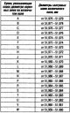
Table of diameter classes of main and connecting rod journals for H4J and M4R engines
Table of journal diameter classes M4R engine H4J engine Table of diameter classes of connecting rod journals M4R engine H4J engine
Table of journal diameter classes M4R engine H4J engine Table of diameter classes of connecting rod journals M4R engine H4J engine

Checking the diameter of the main and connecting rod journals of the crankshaft of the H4J and M4R engines
Checking the diameter of the main journals of the crankshaft Using a micrometer, measure the diameter (in the center of the seat) main journals of the crankshaft, which should be 51.959 - 51.979 mm (for M4R engine) and...
Checking the diameter of the main journals of the crankshaft Using a micrometer, measure the diameter (in the center of the seat) main journals of the crankshaft, which should be 51.959 - 51.979 mm (for M4R engine) and...

Liner selection tables for H4J and M4R engines
M4R engine, main bearing shell selection table (supports 1, 4 and 5) M4R engine, main bearing shell selection table (supports 2 and 3) M4R engine, main bearing shell class table M4R engine, conrod bearing selection...
M4R engine, main bearing shell selection table (supports 1, 4 and 5) M4R engine, main bearing shell selection table (supports 2 and 3) M4R engine, main bearing shell class table M4R engine, conrod bearing selection...

Checking the diametrical clearance between the crankshaft main journals and the bearings of the H4J and M4R engines
Note. Do not rotate the crankshaft while performing this check. Wipe any remaining oil from the main journals and crankshaft bearings on the cylinder block. Install without lubrication: liners of main bearings of a...
Note. Do not rotate the crankshaft while performing this check. Wipe any remaining oil from the main journals and crankshaft bearings on the cylinder block. Install without lubrication: liners of main bearings of a...

Checking the thickness of the adjusting half rings of the crankshaft of the H4J and M4R engines
Using a micrometer, measure the thickness of the adjusting half rings (13), which should be 2.17-2.20 mm (for M4R engine) and 1.90-2.40 mm (for H4J engine).
Using a micrometer, measure the thickness of the adjusting half rings (13), which should be 2.17-2.20 mm (for M4R engine) and 1.90-2.40 mm (for H4J engine).

Checking the axial runout of the crankshaft of the H4J and M4R engines
Install: liners of main bearings of a cranked shaft in the block of cylinders; bearing shells for crankshaft main bearing caps. Note. Lubricate the surfaces of the main bearing shells of the crankshaft in contact with...
Install: liners of main bearings of a cranked shaft in the block of cylinders; bearing shells for crankshaft main bearing caps. Note. Lubricate the surfaces of the main bearing shells of the crankshaft in contact with...

Crankshaft seals for H4J and M4R engines
Crankshaft oil seal on flywheel side Remove the crankshaft seal (1) , using a screwdriver and a piece of wood, being careful not to damage the crankshaft seating surface. Degrease and clean the mating surface of the...
Crankshaft oil seal on flywheel side Remove the crankshaft seal (1) , using a screwdriver and a piece of wood, being careful not to damage the crankshaft seating surface. Degrease and clean the mating surface of the...

Removing the block «piston-rod» H4J and M4R engines
Attention. Do not use a punch or engraver to mark the cylinder affiliation on caps and connecting rods, as this may cause the connecting rod to begin to break. Use an indelible pencil. Mark the position of the...
Attention. Do not use a punch or engraver to mark the cylinder affiliation on caps and connecting rods, as this may cause the connecting rod to begin to break. Use an indelible pencil. Mark the position of the...

Removing piston rings on H4J and M4R engines
Note. This operation should only be performed when replacing or checking piston rings. Remove the piston rings with piston ring pliers. Note. Be careful not to damage the piston when removing the rings. Do not spread...
Note. This operation should only be performed when replacing or checking piston rings. Remove the piston rings with piston ring pliers. Note. Be careful not to damage the piston when removing the rings. Do not spread...

Block «piston-rod» H4J and M4R engines
Disassembly Note. These steps need only be performed when replacing or inspecting a connecting rod or piston. Mark the position of the piston relative to the cylinder with an indelible pencil. Remove the retaining ring...
Disassembly Note. These steps need only be performed when replacing or inspecting a connecting rod or piston. Mark the position of the piston relative to the cylinder with an indelible pencil. Remove the retaining ring...

Piston ring installation for H4J and M4R engines
Note. Observe the position of the piston rings when installing them (mark up). If there are no marks on the piston ring, it can be installed in any position. Install the piston rings with piston ring pliers. Separate...
Note. Observe the position of the piston rings when installing them (mark up). If there are no marks on the piston ring, it can be installed in any position. Install the piston rings with piston ring pliers. Separate...

Installing connecting rod bearing shells for H4J and M4R engines
When replacing the crankshaft, connecting rods, connecting rod bearing shells, it is necessary to determine the thickness class of the bearing shells installed in the connecting rods. Degrease the mating surfaces with a...
When replacing the crankshaft, connecting rods, connecting rod bearing shells, it is necessary to determine the thickness class of the bearing shells installed in the connecting rods. Degrease the mating surfaces with a...
Block installation «piston-rod» H4J and M4R engines
Apply engine oil: into cylinders; piston skirts; on the connecting rod journals of the crankshaft. Make sure the piston rings are properly seated in the piston grooves. Install the piston in the installer (with...
Apply engine oil: into cylinders; piston skirts; on the connecting rod journals of the crankshaft. Make sure the piston rings are properly seated in the piston grooves. Install the piston in the installer (with...
Checking the piston pin length for H4J and M4R engines
Before checking, make sure that the piston pin rotates freely in the piston. Using a micrometer, measure the outer diameter of the piston pin (D) which should be 19.989-19.995 mm.
Before checking, make sure that the piston pin rotates freely in the piston. Using a micrometer, measure the outer diameter of the piston pin (D) which should be 19.989-19.995 mm.

Piston to piston pin clearance for H4J and M4R engines
Using a micrometer, measure the inside diameter of the piston. Piston markings: 1 - piston identification code; 2 - direction of installation of the piston; 3 - piston pin diameter class; 4 - piston class by diameter....
Using a micrometer, measure the inside diameter of the piston. Piston markings: 1 - piston identification code; 2 - direction of installation of the piston; 3 - piston pin diameter class; 4 - piston class by diameter....
Gap between the piston pin and the top head of the connecting rod of the engines H4J and M4R
Using a micrometer, measure the inner diameter of the upper end of the connecting rod. The inner diameter of the connecting rod head must be within 20.000-20.012 mm (for M4R engine) and 20.000 - 20.06 mm (for H4J...
Using a micrometer, measure the inner diameter of the upper end of the connecting rod. The inner diameter of the connecting rod head must be within 20.000-20.012 mm (for M4R engine) and 20.000 - 20.06 mm (for H4J...

Checking the piston skirt diameter of H4J and M4R engines
Using a micrometer, measure the piston diameter (X1) to size (X2) = 39.9 mm. M4R engine H4J engine Checking the clearance between piston grooves and piston rings A: Wrong probe position. B: Correct probe position....
Using a micrometer, measure the piston diameter (X1) to size (X2) = 39.9 mm. M4R engine H4J engine Checking the clearance between piston grooves and piston rings A: Wrong probe position. B: Correct probe position....
Checking the clearance in the lock of the piston rings of the engines H4J and M4R
Install the ring to be tested (7) into the cylinder. advance piston ring (7) to the middle of the cylinder with a piston (8). With a set of probes (9) measure the gap of the ring in the lock. M4R engine: upper...
Install the ring to be tested (7) into the cylinder. advance piston ring (7) to the middle of the cylinder with a piston (8). With a set of probes (9) measure the gap of the ring in the lock. M4R engine: upper...

Connecting rod marking for H4J and M4R engines
Connecting rods with a detachable shear lower head are used. Note. The bushings of the upper heads of the connecting rods are not replaced. Connecting rod marking: 1 - used only by the factory; 2 - cylinder number; 3...
Connecting rods with a detachable shear lower head are used. Note. The bushings of the upper heads of the connecting rods are not replaced. Connecting rod marking: 1 - used only by the factory; 2 - cylinder number; 3...

Checking the diameters of the holes in the upper and lower connecting rod heads of the H4J and M4R engines
Measure with a micrometer: connecting rod bottom diameter (10); connecting rod top diameter. The connecting rod top diameter should be between 20.000-20.012 mm. Note. The bushings of the upper heads of the connecting...
Measure with a micrometer: connecting rod bottom diameter (10); connecting rod top diameter. The connecting rod top diameter should be between 20.000-20.012 mm. Note. The bushings of the upper heads of the connecting...

Checking the diametrical clearance between the crankshaft main journals and the bearings of the H4J and M4R engines
Cut a few pieces of gauge wire to measure the diametral clearance. Lay the gauge wire (11) along the axis of the connecting rod journals of the crankshaft (outside the area of the holes for greasing the bearings). Note....
Cut a few pieces of gauge wire to measure the diametral clearance. Lay the gauge wire (11) along the axis of the connecting rod journals of the crankshaft (outside the area of the holes for greasing the bearings). Note....
This section is available on: russian, bulgarian, belarusian, ukrainian, serbian, croatian, romanian, polish, slovak, hungarian
Other sections on other Renault models
➽ Power unit: Engine repair Renault Laguna 2 (2001-2007)
➽ Power unit: Engine repair Renault Logan 1 (2004-2012, petrol)
➽ Power unit: Engine repair Renault Megan 2 (2002-2009, petrol)
➽ Power unit: Engine repair Renault Scenic 1 (1996-2003)
➽ Power unit: Engine repair Renault Symbol 1 (1999-2008, petrol)
➽ Power unit: Engine repair Renault Espace I and II (1984-1996)
Link to this section in different formats
TEXTHTMLBB Code
- General information
- Maintenance
- Governing bodies
- Car driving
- Power unit
- Engine repair
- Cooling and lubrication system
- Fuel system
- Fuel injection
- Transmission
- Clutch and drive shafts
- Mechanical gearbox
- Automatic gearbox
- Chassis, running gear
- Front suspension
- Rear suspension
- Steering
- Brake system
- Body and interior
- Exterior (external elements)
- Interior (internal elements)
- Doors, locks and windows
- Air conditioning
- Electrical equipment
- Power devices
- Fuses and relays
- Headlights and lighting
- Equipment and devices
- Safety system
- Electrical circuits
RenaultBook.ru © 2018–2024 | Mobile version | News and articles | Sitemap: EN BG BY UA RS HR RO PL SK HU | Administration | Site search | Bookmark
Duster 1 (2009-2017) | Fluence 1 (2009-2020, petrol) | Kangoo 1 (1997-2007) | Laguna 2 (2001-2007) | Logan 1 (2004-2012, petrol) | Logan 2 (2012-2020) | Megane 1 (1995-2002) | Megan 2 (2002-2009, petrol) | Scenic 1 (1996-2003) | Symbol 1 (1999-2008, petrol) | Symbol 2 (2008-2013, petrol) | Renault 19 (1988-1996) | Espace I and II (1984-1996) | Espace III (1996-2002) |