
Share with friends:

Fuel injection system car Renault Fluence 1

Features of the multipoint injection system
The K4M and H4J engines are equipped with a TDC sensor for the first cylinder on the camshaft. Synchronization of the control of system elements with the working process of the engine (determination of the TDC of the...
The K4M and H4J engines are equipped with a TDC sensor for the first cylinder on the camshaft. Synchronization of the control of system elements with the working process of the engine (determination of the TDC of the...
Operation of signal lamps
When starting the engine by pressing the start button «start» The OBD warning light comes on for about 3 seconds and then goes out. In the event of a malfunction in the injection system (1st degree of severity) Written...
When starting the engine by pressing the start button «start» The OBD warning light comes on for about 3 seconds and then goes out. In the event of a malfunction in the injection system (1st degree of severity) Written...

Throttle block
The throttle valve control idle speed and change the amount of air entering the engine. The unit consists of an electric motor and a potentiometric throttle position sensor with two conductive tracks. At idle, the...
The throttle valve control idle speed and change the amount of air entering the engine. The unit consists of an electric motor and a potentiometric throttle position sensor with two conductive tracks. At idle, the...

Camshaft Phase Control
The phase regulator is designed to change the valve timing. To improve the filling of the cylinders with the working mixture in all modes, the engines are equipped with a phase regulator of the intake camshaft. The...
The phase regulator is designed to change the valve timing. To improve the filling of the cylinders with the working mixture in all modes, the engines are equipped with a phase regulator of the intake camshaft. The...

Engine Specifications for Fuel Injection System Diagnostic Procedures (K4M engine)
1 at a coolant temperature above 80°C and a steady engine speed of 2500 rpm for about 30 seconds. 2 91 octane unleaded gasoline is allowed. 3 normalized indicators are determined by the legislation of each particular...
1 at a coolant temperature above 80°C and a steady engine speed of 2500 rpm for about 30 seconds. 2 91 octane unleaded gasoline is allowed. 3 normalized indicators are determined by the legislation of each particular...

Engine Specifications for Fuel Injection System Diagnostic Procedures (M4R engines)
1 at a coolant temperature above 80°C and a steady engine speed of 2500 rpm for about 30 seconds. 2 91 octane unleaded gasoline is allowed. 3 normalized indicators are determined by the legislation of each particular...
1 at a coolant temperature above 80°C and a steady engine speed of 2500 rpm for about 30 seconds. 2 91 octane unleaded gasoline is allowed. 3 normalized indicators are determined by the legislation of each particular...

Intake manifold and throttle body (K4M engine)
Throttle block Remove the engine top cover. Disconnect the throttle body wiring harness at the air line (5). Loosen the tightness: fastening clamp (3) inlet air duct of the throttle valve block; fastening clamp (4)...
Throttle block Remove the engine top cover. Disconnect the throttle body wiring harness at the air line (5). Loosen the tightness: fastening clamp (3) inlet air duct of the throttle valve block; fastening clamp (4)...

Intake manifold and throttle body (M4R engine)
Loosen clamp (1) attaching the air filter housing outlet duct to the throttle valve. Disconnect: hose (2) crankcase ventilation from the cylinder head cover; air filter housing air outlet from the throttle body. Remove...
Loosen clamp (1) attaching the air filter housing outlet duct to the throttle valve. Disconnect: hose (2) crankcase ventilation from the cylinder head cover; air filter housing air outlet from the throttle body. Remove...

Cleaning the throttle body
Attention. Wear protective goggles and gloves when performing this operation. Perform all operations in a clean work area to prevent contamination from entering the throttle body. Remove the throttle body. Remove the...
Attention. Wear protective goggles and gloves when performing this operation. Perform all operations in a clean work area to prevent contamination from entering the throttle body. Remove the throttle body. Remove the...

Engine position and speed sensor
After replacing the crankshaft position and speed sensor or flywheel, program the target area of the flywheel ring gear. Perform two consecutive decelerations in 3rd gear from 4000 rpm until fuel is restored. The fuel...
After replacing the crankshaft position and speed sensor or flywheel, program the target area of the flywheel ring gear. Perform two consecutive decelerations in 3rd gear from 4000 rpm until fuel is restored. The fuel...

Accelerator pedal position sensor
The position sensor forms one assembly with the accelerator pedal. Together with the sensor, the accelerator pedal must also be replaced. Two types of accelerator pedal can be installed on the car: with or without a...
The position sensor forms one assembly with the accelerator pedal. Together with the sensor, the accelerator pedal must also be replaced. Two types of accelerator pedal can be installed on the car: with or without a...

Oxygen sensors
Upstream oxygen sensor Remove the oxygen sensor (1) using a device (Mot. 1495-01). Downstream oxygen sensor Remove the oxygen sensor (1). The sensors are installed in the reverse order of removal. Torque tighten (45 Nm)...
Upstream oxygen sensor Remove the oxygen sensor (1) using a device (Mot. 1495-01). Downstream oxygen sensor Remove the oxygen sensor (1). The sensors are installed in the reverse order of removal. Torque tighten (45 Nm)...

Turbocharger cooler outlet air line (H4J engine)
Remove: top cover of the engine; engine crankcase mounting bolts; protective screen. Disconnect the cooler outlet air line from the mounting bracket. Slide the cooler air outlet duct bracket to the side by pulling on...
Remove: top cover of the engine; engine crankcase mounting bolts; protective screen. Disconnect the cooler outlet air line from the mounting bracket. Slide the cooler air outlet duct bracket to the side by pulling on...

Intake muffler (H4J engine)
Remove: front wheels; the front of the front fender liner; front bumper; left headlight. Disconnect the exhaust duct from the intake silencer (1). Disconnect the intake silencer connectors (2). Remove the intake...
Remove: front wheels; the front of the front fender liner; front bumper; left headlight. Disconnect the exhaust duct from the intake silencer (1). Disconnect the intake silencer connectors (2). Remove the intake...

Air duct between cooler and turbocharger (H4J engine)
Remove the engine top cover. Remove the crankcase ventilation hose clamp (1) on the cylinder head cover with remote gripping pliers for elastic bands (Mot. 1448). Disconnect: crankcase ventilation hose from the cylinder...
Remove the engine top cover. Remove the crankcase ventilation hose clamp (1) on the cylinder head cover with remote gripping pliers for elastic bands (Mot. 1448). Disconnect: crankcase ventilation hose from the cylinder...
Heat shield and turbocharger oil line (H4J engine)
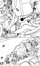
Remove: bolts (1) fixing the heat shield of the turbocharger; nut (2) fixing the heat shield of the turbocharger; turbocharger heat shield. Attention. To avoid overheating of the surrounding elements, do not damage the...
Remove: bolts (1) fixing the heat shield of the turbocharger; nut (2) fixing the heat shield of the turbocharger; turbocharger heat shield. Attention. To avoid overheating of the surrounding elements, do not damage the...

Turbocharger (H4J engine)
Disconnect connector (1) boost pressure regulator solenoid valve. Remove: collar (2) from the inlet hose of the solenoid valve for controlling the pneumatic drive of the boost pressure regulator; collar (3) from the...
Disconnect connector (1) boost pressure regulator solenoid valve. Remove: collar (2) from the inlet hose of the solenoid valve for controlling the pneumatic drive of the boost pressure regulator; collar (3) from the...

Charge air cooler (H4J engine)
Remove the top and side air baffles. Loosen the mounting bolt (1) cooler air supply line. Remove: holder (2) fastening of the inlet air duct of the cooler; cooler air supply line. Remove: collar (3) fixing the outlet...
Remove the top and side air baffles. Loosen the mounting bolt (1) cooler air supply line. Remove: holder (2) fastening of the inlet air duct of the cooler; cooler air supply line. Remove: collar (3) fixing the outlet...
Knock sensor
Remove the engine cover front bracket. Disconnect the alternator wiring from the oil dipstick tube. Loosen the oil dipstick tube mounting bolts. Move aside the oil dipstick guide tube. Disconnect the knock sensor...
Remove the engine cover front bracket. Disconnect the alternator wiring from the oil dipstick tube. Loosen the oil dipstick tube mounting bolts. Move aside the oil dipstick guide tube. Disconnect the knock sensor...

Camshaft position sensor (except M4R engine)
Remove the engine top cover. Disconnect connector (1) camshaft position sensor. Remove: bolt (2) mounting the camshaft position sensor; camshaft position sensor and its gasket. When installing, torque tighten the...
Remove the engine top cover. Disconnect connector (1) camshaft position sensor. Remove: bolt (2) mounting the camshaft position sensor; camshaft position sensor and its gasket. When installing, torque tighten the...

An exhaust manifold (K4M engine)
Place the car on a lift. Disconnect the battery. Remove the engine top cover. Remove: windshield wiper arms; air intake grille; a box under the grille of the air intake niche. Remove the throttle body. Remove ignition...
Place the car on a lift. Disconnect the battery. Remove the engine top cover. Remove: windshield wiper arms; air intake grille; a box under the grille of the air intake niche. Remove the throttle body. Remove ignition...

An exhaust manifold (M4R engine)
Place the car on a lift. Disconnect the battery. Remove: engine undertray protection; intake manifold. Remove: exhaust manifold bracket bolts (1); exhaust manifold bracket. Loosen the mounting bolts (2) exhaust pipe...
Place the car on a lift. Disconnect the battery. Remove: engine undertray protection; intake manifold. Remove: exhaust manifold bracket bolts (1); exhaust manifold bracket. Loosen the mounting bolts (2) exhaust pipe...

Toxicity reduction system
Attention. Under normal operating conditions, the opening for communication with the atmosphere should be open. Communication with the atmosphere of the fuel tank is carried out through the adsorber (vapor trap)....
Attention. Under normal operating conditions, the opening for communication with the atmosphere should be open. Communication with the atmosphere of the fuel tank is carried out through the adsorber (vapor trap)....

Removing and checking the adsorber (all engines)
The adsorber is mounted on the fuel tank under the vehicle. Release adsorber (1) out of the latch on the fuel tank by moving it in the direction of the arrow. Disconnect the vapor lines from the fuel tank supplying...
The adsorber is mounted on the fuel tank under the vehicle. Release adsorber (1) out of the latch on the fuel tank by moving it in the direction of the arrow. Disconnect the vapor lines from the fuel tank supplying...
Crankcase ventilation system (all engines)
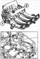
At low loads, oil vapors are sucked in small quantities through a calibrated orifice. At medium and high loads, oil vapors are sucked in large quantities through the throttle valve. To ensure proper operation of the...
At low loads, oil vapors are sucked in small quantities through a calibrated orifice. At medium and high loads, oil vapors are sucked in large quantities through the throttle valve. To ensure proper operation of the...

Exhaust gas exhaust system
Catalytic converter (M4R engine) Place the car on a lift. Disconnect the battery. Disconnect the connector from the holder (1) upstream oxygen sensor of the catalytic converter. Disconnect the upstream oxygen sensor...
Catalytic converter (M4R engine) Place the car on a lift. Disconnect the battery. Disconnect the connector from the holder (1) upstream oxygen sensor of the catalytic converter. Disconnect the upstream oxygen sensor...
This section is available on: russian, bulgarian, belarusian, ukrainian, serbian, croatian, romanian, polish, slovak, hungarian
Other sections on other Renault models
➽ Power unit: Diesel injection system (K9K) Renault Duster 1 (2009-2017)
➽ Power unit: Fuel injection (petrol) Renault Laguna 2 (2001-2007)
➽ Power unit: Injection system Renault Megan 2 (2002-2009, petrol)
➽ Power unit: Injection system (petrol) Renault Scenic 1 (1996-2003)
➽ Power unit: Injection fuel system Renault Espace I and II (1984-1996)
Link to this section in different formats
TEXTHTMLBB Code
- General information
- Maintenance
- Governing bodies
- Car driving
- Power unit
- Engine repair
- Cooling and lubrication system
- Fuel system
- Fuel injection
- Transmission
- Clutch and drive shafts
- Mechanical gearbox
- Automatic gearbox
- Chassis, running gear
- Front suspension
- Rear suspension
- Steering
- Brake system
- Body and interior
- Exterior (external elements)
- Interior (internal elements)
- Doors, locks and windows
- Air conditioning
- Electrical equipment
- Power devices
- Fuses and relays
- Headlights and lighting
- Equipment and devices
- Safety system
- Electrical circuits
RenaultBook.ru © 2018–2024 | Mobile version | News and articles | Sitemap: EN BG BY UA RS HR RO PL SK HU | Administration | Site search | Bookmark
Duster 1 (2009-2017) | Fluence 1 (2009-2020, petrol) | Kangoo 1 (1997-2007) | Laguna 2 (2001-2007) | Logan 1 (2004-2012, petrol) | Logan 2 (2012-2020) | Megane 1 (1995-2002) | Megan 2 (2002-2009, petrol) | Scenic 1 (1996-2003) | Symbol 1 (1999-2008, petrol) | Symbol 2 (2008-2013, petrol) | Renault 19 (1988-1996) | Espace I and II (1984-1996) | Espace III (1996-2002) |