



Share with friends:
Fuel injection system car Renault Megane 2

Features of the Sagem S3000 multipoint injection system
Fig. 2.225. Location of injection system elements in the engine compartment of a Megane II with a K4J engine: 1 – fuel vapor recirculation electromagnetic valve; 2 – absolute pressure sensor; 3 – throttle valve unit...
Fig. 2.225. Location of injection system elements in the engine compartment of a Megane II with a K4J engine: 1 – fuel vapor recirculation electromagnetic valve; 2 – absolute pressure sensor; 3 – throttle valve unit...

Fuel mixture control (F4R, K4M)
Heating of sensors The oxygen sensor heating is switched on by the ECU when the following conditions are met: the intake pressure is below a certain threshold, depending on the engine speed; speed below 135 km/h; after...
Heating of sensors The oxygen sensor heating is switched on by the ECU when the following conditions are met: the intake pressure is below a certain threshold, depending on the engine speed; speed below 135 km/h; after...

Camshaft phase regulator (F4R, K4M)
The phase regulator is designed to change the valve timing. Fig. 2.228. Camshaft phase regulator: 1 – phase regulator To improve the filling of the cylinders with the working mixture in all modes, the K4M and F4R...
The phase regulator is designed to change the valve timing. Fig. 2.228. Camshaft phase regulator: 1 – phase regulator To improve the filling of the cylinders with the working mixture in all modes, the K4M and F4R...

Phase regulator operating modes (K4M)
Fig. 2.229. Phase regulator electromagnetic valve: 1 – valve Oil is supplied to the phase regulator via an electromagnetic valve installed on the cylinder head (fig. 2.229). The valve is supplied with electrical power...
Fig. 2.229. Phase regulator electromagnetic valve: 1 – valve Oil is supplied to the phase regulator via an electromagnetic valve installed on the cylinder head (fig. 2.229). The valve is supplied with electrical power...

Operation and control of the phase regulator (F4R)
Fig. 2.230. Phase regulator electromagnetic valve: 1 – valve The phase regulator is disabled or controlled by the injection system ECU via an electromagnetic valve installed on the cylinder head cover (fig. 2.230). When...
Fig. 2.230. Phase regulator electromagnetic valve: 1 – valve The phase regulator is disabled or controlled by the injection system ECU via an electromagnetic valve installed on the cylinder head cover (fig. 2.230). When...

Removal and installation oxygen sensors
Upstream oxygen sensors Fig. 2.231. Removing the upper oxygen sensor: 1 – sensor Remove the oxygen sensor using the tool (Mot. 1495-01) (fig. 2.231). Downstream Oxygen Sensors - Removal and Installation Fig. 2.232....
Upstream oxygen sensors Fig. 2.231. Removing the upper oxygen sensor: 1 – sensor Remove the oxygen sensor using the tool (Mot. 1495-01) (fig. 2.231). Downstream Oxygen Sensors - Removal and Installation Fig. 2.232....

Removal and installation the accelerator pedal position sensor
The position sensor forms a single unit with the accelerator pedal. The accelerator pedal must be replaced together with the sensor. The vehicle can be equipped with two types of accelerator pedal: with or without a...
The position sensor forms a single unit with the accelerator pedal. The accelerator pedal must be replaced together with the sensor. The vehicle can be equipped with two types of accelerator pedal: with or without a...

Crankshaft position and speed sensor
After replacing the crankshaft position and speed sensor or flywheel, program the flywheel ring gear target area. Perform two consecutive decelerations in 3rd gear from an engine speed of 4000 min⁻¹ until the fuel...
After replacing the crankshaft position and speed sensor or flywheel, program the flywheel ring gear target area. Perform two consecutive decelerations in 3rd gear from an engine speed of 4000 min⁻¹ until the fuel...

Removal and installation of the ECU of the petrol engine injection system
Removal Remove the top engine covers. Disconnect the wires from the battery terminals, starting with the negative terminal. Disconnect the fuel injection system ECU connectors. Fig. 2.235. Location of the ECU: 1 –...
Removal Remove the top engine covers. Disconnect the wires from the battery terminals, starting with the negative terminal. Disconnect the fuel injection system ECU connectors. Fig. 2.235. Location of the ECU: 1 –...

Removal and installation the throttle body (K4J)
Removal Disconnect the wires from the battery terminals, starting with the negative terminal. Remove the air filter housing. Fig. 2.236. Disconnecting the wiring block from the throttle valve unit and the fuel vapor...
Removal Disconnect the wires from the battery terminals, starting with the negative terminal. Remove the air filter housing. Fig. 2.236. Disconnecting the wiring block from the throttle valve unit and the fuel vapor...

Removal and installation the throttle valve unit (K4M)
Removal Disconnect the wires from the battery terminals, starting with the negative terminal. Fig. 2.238. Removing the air duct: 1 – air duct Remove the air duct (fig. 2.238). Disconnect the wiring harness from the...
Removal Disconnect the wires from the battery terminals, starting with the negative terminal. Fig. 2.238. Removing the air duct: 1 – air duct Remove the air duct (fig. 2.238). Disconnect the wiring harness from the...

Removal and installation the throttle body (F4R)
Removal Remove the top engine covers. Move the air duct aside. Fig. 2.240. Removing the fuel vapor recovery system hose: 1 – air duct; 2 – fuel vapor recovery system hose Remove the fuel vapor recovery system hose (fig....
Removal Remove the top engine covers. Move the air duct aside. Fig. 2.240. Removing the fuel vapor recovery system hose: 1 – air duct; 2 – fuel vapor recovery system hose Remove the fuel vapor recovery system hose (fig....

Cleaning the throttle body
Caution! When performing this operation, wear protective glasses and gloves. Perform all actions in a clean work area to prevent contamination from entering the throttle valve unit. Remove the throttle body. Fig. 2.242....
Caution! When performing this operation, wear protective glasses and gloves. Perform all actions in a clean work area to prevent contamination from entering the throttle valve unit. Remove the throttle body. Fig. 2.242....

Engine characteristics for injection system diagnostic procedures
Engine Specifications for Fuel Injection System Diagnostic Procedures (k4J, K4M engines) *1 when the coolant temperature is above 80°C and the engine speed is steady at 2500 min⁻¹ for approximately 30 s. *2 Unleaded...
Engine Specifications for Fuel Injection System Diagnostic Procedures (k4J, K4M engines) *1 when the coolant temperature is above 80°C and the engine speed is steady at 2500 min⁻¹ for approximately 30 s. *2 Unleaded...
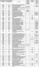
Diagnostics of injection system faults
Troubleshooting ECU name: Sagem S3000 Program number: A7 Diagnostic software version number (Vdiag): 44 Troubleshooting ECU name: Sagem S3000 Program number: AD Diagnostic software version number (Vdiag): 4C
Troubleshooting ECU name: Sagem S3000 Program number: A7 Diagnostic software version number (Vdiag): 44 Troubleshooting ECU name: Sagem S3000 Program number: AD Diagnostic software version number (Vdiag): 4C
This section is available on: russian, bulgarian, belarusian, ukrainian, serbian, croatian, romanian, polish, slovak, hungarian
Other sections on other Renault models
➽ Power unit: Fuel injection Renault Fluence 1 (2009-2020, petrol)
➽ Power unit: Injection system (petrol) Renault Scenic 1 (1996-2003)
➽ Power unit: Diesel injection system Renault 19 (1988-1996)
➽ Power unit: Petrol injection system (K4M) Renault Duster 1 (2009-2017)
➽ Power unit: Fuel injection (petrol) Renault Laguna 2 (2001-2007)
Link to this section in different formats
TEXTHTMLBB Code
- User manual
- Introduction to manual
- Controls and instruments
- Salon equipment
- Operation and driving
- Maintenance and care
- Power unit
- Engine repair
- Fuel system
- Injection system
- Intake and exhaust system
- Starting and charging system
- Cooling system
- Decreased toxicity
- Transmission
- Clutch
- Mechanical gearbox
- Automatic gearbox
- Wheel drive mechanism
- Chassis, running gear
- Suspension and wheels
- Steering
- Brake system
- Body and interior
- Exterior (external elements)
- Interior (internal elements)
- Doors, locks and windows
- Heating and air conditioning
- Electrical equipment
- Equipment and devices
- Headlights and lighting
- Electrical circuits
- General information
- User manual
- Maintenance
- Power unit
- Petrol engines 1.4/1.6 l
- Petrol engines 2.0 l
- Diesel engines 1.9 l
- Overhaul of engines
- Cooling system
- Fuel system (petrol)
- Fuel system (diesel)
- Decreased toxicity
- Charge and launch systems
- Ignition system (petrol)
- Preheat system (diesel)
- Transmission
- Clutch
- Mechanical gearbox
- Automatic gearbox
- Drive shafts
- Chassis, running gear
- Brake system
- Car suspension
- Steering
- Body and interior
- Exterior (external elements)
- Interior (internal elements)
- Doors, locks and windows
- Electrical equipment
- Equipment and devices
- Electrical circuits