
Share with friends:

Brake system of the car Renault Fluence 1
General information about the brake system
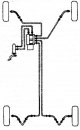
General information The vehicle is equipped with two diagonal brake circuits. One circuit uses the front right and rear left wheels, the second circuit uses the front left and rear right wheels. When only one of the...
General information The vehicle is equipped with two diagonal brake circuits. One circuit uses the front right and rear left wheels, the second circuit uses the front left and rear right wheels. When only one of the...

Brake components
Vacuum brake booster The vacuum brake booster reduces the force on the brake pedal, making it easier to drive. The vacuum amplifier uses a diaphragm, on both sides of which a vacuum is created during normal operation....
Vacuum brake booster The vacuum brake booster reduces the force on the brake pedal, making it easier to drive. The vacuum amplifier uses a diaphragm, on both sides of which a vacuum is created during normal operation....

Precautions when working with the brake system
Do not depress the brake pedal when working on the brake system. If damage to any part is detected during work on the brake system, the malfunction must be eliminated before the vehicle is put into operation. Brake...
Do not depress the brake pedal when working on the brake system. If damage to any part is detected during work on the brake system, the malfunction must be eliminated before the vehicle is put into operation. Brake...
Specifications of the brake system
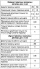
* Brake discs are not subject to grinding. In case of severe wear or deep scratches, the discs must be replaced.
* Brake discs are not subject to grinding. In case of severe wear or deep scratches, the discs must be replaced.

Tightening torques for brake system components
Front brakes Rear brakes Hydraulic brake
Front brakes Rear brakes Hydraulic brake

Removal of air from the hydraulic drive of the working brake system
Bleeding the brakes Bleeding from the hydraulic drive of the working brake system is necessary to remove air, which significantly reduces the braking efficiency. Air can get into the hydraulic drive due to...
Bleeding the brakes Bleeding from the hydraulic drive of the working brake system is necessary to remove air, which significantly reduces the braking efficiency. Air can get into the hydraulic drive due to...
Bleeding the pressure control circuit
This operation is performed after removing or replacing one of the following items: master brake cylinder; hydroblock; brake fluid; hydraulic brake reservoir. Place the car on a lift. Connect: a device for removing air...
This operation is performed after removing or replacing one of the following items: master brake cylinder; hydroblock; brake fluid; hydraulic brake reservoir. Place the car on a lift. Connect: a device for removing air...

Automatic parking brake (configuration option)
The automatic parking brake system includes: Control block; lever arm; electric motors. Note. The automatic parking brake motor is not supplied with a repair kit. If the motor is defective, replace the motor assembly...
The automatic parking brake system includes: Control block; lever arm; electric motors. Note. The automatic parking brake motor is not supplied with a repair kit. If the motor is defective, replace the motor assembly...

Checking the parking brake cable
Place the car on a lift. Check the position of the power parking brake cable. If the power parking brake cable is secured, install the band clamp. If the parking brake cable with booster is loose, check the condition of...
Place the car on a lift. Check the position of the power parking brake cable. If the power parking brake cable is secured, install the band clamp. If the parking brake cable with booster is loose, check the condition of...

Replacing the parking brake cable (vehicles without automatic parking brake)
Place the car on a lift. Remove the mat (1) center console. Loosen the fixing screws (1) center console and remove it. Loosen the adjusting nut (1), disconnect the parking brake cables (2) in the area of the drive...
Place the car on a lift. Remove the mat (1) center console. Loosen the fixing screws (1) center console and remove it. Loosen the adjusting nut (1), disconnect the parking brake cables (2) in the area of the drive...

Replacing the automatic parking brake computer
Place the car on a flat horizontal platform. Engage 1st gear. Install the block behind the rear wheel. Release the automatic parking brake using the lever. Carry out operations with the diagnostic tool «CLIP»: connect...
Place the car on a flat horizontal platform. Engage 1st gear. Install the block behind the rear wheel. Release the automatic parking brake using the lever. Carry out operations with the diagnostic tool «CLIP»: connect...
Parking brake lever adjustment
Remove the center console. Gradually tighten the drive cables by turning the adjusting nut (1) parking brake lever until the tip touches the lever without moving it. Correct the adjustment so that the expansion levers...
Remove the center console. Gradually tighten the drive cables by turning the adjusting nut (1) parking brake lever until the tip touches the lever without moving it. Correct the adjustment so that the expansion levers...

Replacing the brake light switch
Remove the bottom trim of the dashboard. Disconnect the brake light switch connector (1). Rotate stop light switch (2) one eighth of a turn counterclockwise. Remove the stoplight switch. Disconnect the brake light...
Remove the bottom trim of the dashboard. Disconnect the brake light switch connector (1). Rotate stop light switch (2) one eighth of a turn counterclockwise. Remove the stoplight switch. Disconnect the brake light...

Replacing the front brake pads
Place the car on a lift. Unlock the steering wheel. Remove the front wheels. Remove the spring (1) with front caliper and brake hose (2) from the shock absorber. Remove the two caps from the guide pins. Loosen the...
Place the car on a lift. Unlock the steering wheel. Remove the front wheels. Remove the spring (1) with front caliper and brake hose (2) from the shock absorber. Remove the two caps from the guide pins. Loosen the...

Front brake caliper
Note. The brake calipers are supplied in a repair kit with a cylinder filled with brake fluid. When replacing the brake pads or brake disc, be sure to replace them on both sides of the vehicle. Place the car on a lift....
Note. The brake calipers are supplied in a repair kit with a cylinder filled with brake fluid. When replacing the brake pads or brake disc, be sure to replace them on both sides of the vehicle. Place the car on a lift....

Guide of the front brake pads
Place the car on a lift. Remove the front wheels. Loosen the mounting bolts (1) guide pins (2). Hang the caliper from the suspension spring. Remove the brake pads. Remove the two bolts securing the guide pads. Remove...
Place the car on a lift. Remove the front wheels. Loosen the mounting bolts (1) guide pins (2). Hang the caliper from the suspension spring. Remove the brake pads. Remove the two bolts securing the guide pads. Remove...

Front brake disc
Note. Brake discs cannot be sanded. In case of significant wear or deep scratches, the discs must be replaced. When replacing the brake discs, also replace the brake pads. Place the car on a lift. Unlock the steering...
Note. Brake discs cannot be sanded. In case of significant wear or deep scratches, the discs must be replaced. When replacing the brake discs, also replace the brake pads. Place the car on a lift. Unlock the steering...

Front brake hose
Attention. Take measures to collect the brake fluid to prevent damage to mechanical parts and body parts located near the elements of the brake system. Install a pressurizer on the brake pedal to reduce the amount of...
Attention. Take measures to collect the brake fluid to prevent damage to mechanical parts and body parts located near the elements of the brake system. Install a pressurizer on the brake pedal to reduce the amount of...

Replacing the rear brake pads
Check pad thickness. To do this, raise the car, remove the wheel and look through the inspection hole in the cylinder body. Minimum thickness of brake pads: 1 mm. Limit wear: 2.0 mm. Place the car on a lift. Remove rear...
Check pad thickness. To do this, raise the car, remove the wheel and look through the inspection hole in the cylinder body. Minimum thickness of brake pads: 1 mm. Limit wear: 2.0 mm. Place the car on a lift. Remove rear...
Rear brake caliper
Note. The brake calipers are supplied in a repair kit with a cylinder filled with brake fluid. When replacing the brake pads or brake disc, be sure to replace the pads or disc on the other side of the vehicle. The...
Note. The brake calipers are supplied in a repair kit with a cylinder filled with brake fluid. When replacing the brake pads or brake disc, be sure to replace the pads or disc on the other side of the vehicle. The...

Guide of the rear brake pads
Place the car on a lift. Release the parking brake. Remove the rear wheel. Release the parking brake cable. Mark the cable route for subsequent installation. Turn away bolts of fastening of directing fingers. Remove the...
Place the car on a lift. Release the parking brake. Remove the rear wheel. Release the parking brake cable. Mark the cable route for subsequent installation. Turn away bolts of fastening of directing fingers. Remove the...

Rear brake disc
Note. Brake discs cannot be sanded. In case of significant wear or deep scratches, the discs must be replaced. When replacing the brake discs, also replace the brake pads. Place the car on a lift. Remove wheels. Release...
Note. Brake discs cannot be sanded. In case of significant wear or deep scratches, the discs must be replaced. When replacing the brake discs, also replace the brake pads. Place the car on a lift. Remove wheels. Release...

Rigid brake line
Place the car on a lift. Install a pressurizer on the brake pedal to reduce the amount of brake fluid escaping. Raise the vehicle. Rigid pipe left rear brake Unscrew the rigid pipeline (1) in the area of the rear...
Place the car on a lift. Install a pressurizer on the brake pedal to reduce the amount of brake fluid escaping. Raise the vehicle. Rigid pipe left rear brake Unscrew the rigid pipeline (1) in the area of the rear...

Rigid Brake Line Repair
Note. This method is used for copper pipelines with a diameter of 4.7 mm. This method is not applicable: for hybrid pipelines (rigid tube + hose); for pipelines with a diameter of 6 mm and 8 mm. Cut the tubing to the...
Note. This method is used for copper pipelines with a diameter of 4.7 mm. This method is not applicable: for hybrid pipelines (rigid tube + hose); for pipelines with a diameter of 6 mm and 8 mm. Cut the tubing to the...

Brake pedal
Switch off the ignition. Disconnect the brake light switch. Remove the bottom trim of the dashboard. Remove: brake pedal buffer bolt (1); brake pedal buffer (2). Remove rubber bushing (3) with connecting shaft with...
Switch off the ignition. Disconnect the brake light switch. Remove the bottom trim of the dashboard. Remove: brake pedal buffer bolt (1); brake pedal buffer (2). Remove rubber bushing (3) with connecting shaft with...

Master brake cylinder
Place the car on a lift. Remove: battery; battery shelf; air filter housing. Remove the brake fluid from the reservoir with a syringe. Substitute the container for the brake fluid that remains in the master cylinder....
Place the car on a lift. Remove: battery; battery shelf; air filter housing. Remove the brake fluid from the reservoir with a syringe. Substitute the container for the brake fluid that remains in the master cylinder....

Vacuum brake booster
The operation of the vacuum brake booster, located on the engine shield, is based on the use of intake manifold vacuum and atmospheric air pressure. After completing each operation, which included the removal of any of...
The operation of the vacuum brake booster, located on the engine shield, is based on the use of intake manifold vacuum and atmospheric air pressure. After completing each operation, which included the removal of any of...

Vacuum brake booster — removal
Remove decorative covers. Disconnect the wires from the battery terminals, starting with the negative terminal. Remove the battery. Remove the air resonator. Remove the battery tray. Remove the injection computer....
Remove decorative covers. Disconnect the wires from the battery terminals, starting with the negative terminal. Remove the battery. Remove the air resonator. Remove the battery tray. Remove the injection computer....
Checking the operation of the check valve of the vacuum brake booster
Check on the non-return valve installed in the vacuum hose. Remove the brake booster vacuum hose. Note. The non-return valve is installed with an interference fit in the vacuum hose according to the alignment marks....
Check on the non-return valve installed in the vacuum hose. Remove the brake booster vacuum hose. Note. The non-return valve is installed with an interference fit in the vacuum hose according to the alignment marks....

Removing the brake booster check valve
Remove the engine top covers. Loosen the air duct clamps and remove the air duct. Disconnect the suction hose (1) from the vacuum brake booster. Pull the check valve out by rotating it to remove it from the rubber...
Remove the engine top covers. Loosen the air duct clamps and remove the air duct. Disconnect the suction hose (1) from the vacuum brake booster. Pull the check valve out by rotating it to remove it from the rubber...

Anti-Lock Braking System (ABS) — general information
The car is equipped with ABS BOSCH 8.0. Depending on the vehicle equipment level, the BOSCH 8.0 system includes only ABS brakes or ABS combined with a trajectory stabilization system (SST). Note. After carrying out any...
The car is equipped with ABS BOSCH 8.0. Depending on the vehicle equipment level, the BOSCH 8.0 system includes only ABS brakes or ABS combined with a trajectory stabilization system (SST). Note. After carrying out any...

Removal and installation of the hydraulic block — removal
Place the car on a lift. Disconnect the battery. Install a tool on the brake pedal to measure the amount of brake fluid escaping. Drain the refrigerant from the refrigeration circuit. Remove the engine top covers....
Place the car on a lift. Disconnect the battery. Install a tool on the brake pedal to measure the amount of brake fluid escaping. Drain the refrigerant from the refrigeration circuit. Remove the engine top covers....

Removal and installation of the hydraulic block — installation
Installation is made in an order, the return to removal. Attention. Point the tip of the wire «masses» valve body down to ensure the tightness of the valve body ECU connector. Install the air conditioning refrigeration...
Installation is made in an order, the return to removal. Attention. Point the tip of the wire «masses» valve body down to ensure the tightness of the valve body ECU connector. Install the air conditioning refrigeration...

Electric pump assembly
Deciphering the designations of the circuit diagram of the electric pump Schematic diagram of the electric pump Designation and type of electric pump circuit Note. Two types of electric pumps can be installed,...
Deciphering the designations of the circuit diagram of the electric pump Schematic diagram of the electric pump Designation and type of electric pump circuit Note. Two types of electric pumps can be installed,...

ABS ECU — replacement
Place the car on a lift. Remove the hydroblock assembly. Loosen the fixing screws (1) ECU on the pressure control unit and remove the ECU (2). Do not clean the pressure control unit. Be sure to replace the ECU mounting...
Place the car on a lift. Remove the hydroblock assembly. Loosen the fixing screws (1) ECU on the pressure control unit and remove the ECU (2). Do not clean the pressure control unit. Be sure to replace the ECU mounting...

Front wheel speed sensor
Remove the front wheel and front fender liner. Disconnect the wheel speed sensor wiring harness (1). Release the wheel speed sensor wire from the holder in the area (2). Remove mounting bolt (3) and wheel speed sensor...
Remove the front wheel and front fender liner. Disconnect the wheel speed sensor wiring harness (1). Release the wheel speed sensor wire from the holder in the area (2). Remove mounting bolt (3) and wheel speed sensor...

Rear wheel speed sensor
Remove the rear wheel. Disconnect the wheel speed sensor (1) from its holder. Release the wheel speed sensor wire from the holder in the area (2). Disconnect the wheel speed sensor wiring harness (3) and remove the...
Remove the rear wheel. Disconnect the wheel speed sensor (1) from its holder. Release the wheel speed sensor wire from the holder in the area (2). Disconnect the wheel speed sensor wiring harness (3) and remove the...
This section is available on: russian, bulgarian, belarusian, ukrainian, serbian, croatian, romanian, polish, slovak, hungarian
Other sections on other Renault models
➽ Chassis, running gear: Brake system Renault Kangoo 1 (1997-2007)
➽ Chassis, running gear: Brake system Renault Laguna 2 (2001-2007)
➽ Chassis, running gear: Brake system Renault Logan 2 (2012-2020)
➽ Chassis, running gear: Brake system Renault Megane 1 (1995-2002)
➽ Chassis, running gear: Brake system Renault Scenic 1 (1996-2003)
➽ Chassis, running gear: Brake system Renault Symbol 1 (1999-2008, petrol)
➽ Chassis, running gear: Brake system Renault Espace III (1996-2002)
Link to this section in different formats
TEXTHTMLBB Code
- General information
- Maintenance
- Governing bodies
- Car driving
- Power unit
- Engine repair
- Cooling and lubrication system
- Fuel system
- Fuel injection
- Transmission
- Clutch and drive shafts
- Mechanical gearbox
- Automatic gearbox
- Chassis, running gear
- Front suspension
- Rear suspension
- Steering
- Brake system
- Body and interior
- Exterior (external elements)
- Interior (internal elements)
- Doors, locks and windows
- Air conditioning
- Electrical equipment
- Power devices
- Fuses and relays
- Headlights and lighting
- Equipment and devices
- Safety system
- Electrical circuits
RenaultBook.ru © 2018–2024 | Mobile version | News and articles | Sitemap: EN BG BY UA RS HR RO PL SK HU | Administration | Site search | Bookmark
Duster 1 (2009-2017) | Fluence 1 (2009-2020, petrol) | Kangoo 1 (1997-2007) | Laguna 2 (2001-2007) | Logan 1 (2004-2012, petrol) | Logan 2 (2012-2020) | Megane 1 (1995-2002) | Megan 2 (2002-2009, petrol) | Scenic 1 (1996-2003) | Symbol 1 (1999-2008, petrol) | Symbol 2 (2008-2013, petrol) | Renault 19 (1988-1996) | Espace I and II (1984-1996) | Espace III (1996-2002) |