



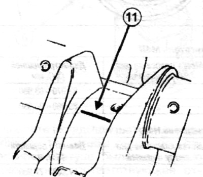
Place the calibrated wire (11) along the axis of the crankshaft connecting rod journals (outside the area of the lubrication holes for the supports).
Note: Do not rotate the connecting rod or crankshaft while performing the following steps.
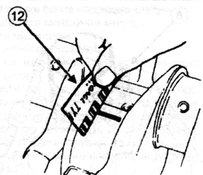
Install the connecting rod-piston assembly. Remove the connecting rod-piston assembly. By flattening the calibrated wire, determine the clearance between the bearing shells and the main journals using the scale applied to the wire package (12).
Check the gap size, which should be within 0.037-0.07 mm.
[Original publication on the website www.RenaultBook.ru]
Clean the crankshaft and main bearing shells from any traces of calibrated wire.
Checking the axial movement of the connecting rod
Using a set of feeler gauges, make sure that the clearance between the connecting rod and the crankshaft is 0.20-0.352 mm.