
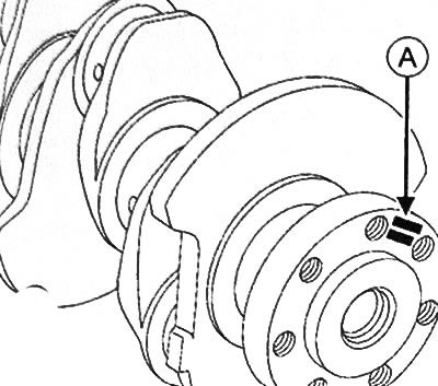
A. Crankshaft identification stamp
Deciphering the identification stamp of the crankshaft: 1. Size groups of crankshaft main journals. 2. Dimensional groups of connecting rod journals of the crankshaft. 3. Dimensional group of the root neck No. 1 (flywheel side). 4. Dimensional group of the root neck No. 5 (the drive side of the gas distribution mechanism).5. Dimensional group of connecting rod neck No. 1 (flywheel side). 6. Dimensional group of connecting rod neck No. 5 (the drive side of the gas distribution mechanism).
Correspondence between size groups and diameters of crankshaft main journals
| Size group | Crankshaft journal diameter |
| A or D | 47.990-47.996 mm |
| B or E | 47.997-48.003 mm |
| C or F | 48.004-48.010 mm |
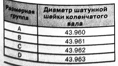
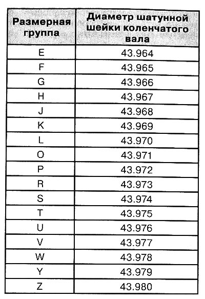
Correspondence between size groups and diameters of the connecting rod journals of the crankshaft
1. Remove the crankshaft from the engine.
2. Clean crankshaft with cleaning agent and dry with compressed air.
3. Check that the crankshaft is free from scratches, impact marks, or abnormal wear. If any defects are found, replace the crankshaft with a new one.
4. Measure the diameter of the crankshaft main journals with a micrometer. This value should be 47.990~48.010mm.
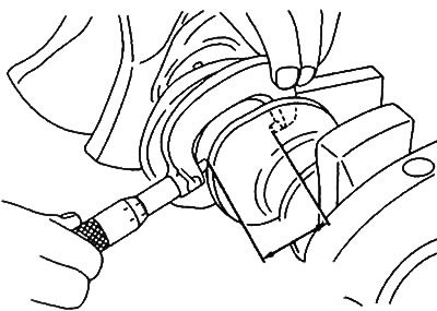
5. Determine the size groups for the corresponding crankshaft main journals.
6. Using a micrometer, measure the diameter of the connecting rod journals of the crankshaft. This value should be 43.960~43.980mm.
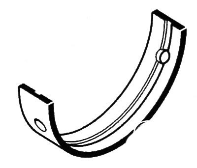
Note: The main bearing shells do not have any alignment lugs or grooves.
7. Install the crankshaft main bearing shells using a special tool (Mot. 1493-01):
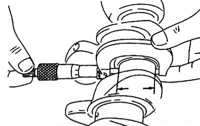
- Grooved bushings are installed in No. 2 and No. 4 main bearing caps.
- Non-grooved bushings are installed in main bearing caps Nos. 1, 3 and 5.
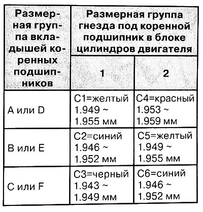
Correspondence between size groups and thicknesses of main bearing shells
8. Remove oil from the crankshaft main journals and from the main bearing shells in the cylinder block.
9. Install the crankshaft without lubrication.
Note: Do not rotate the crankshaft while checking.
10. Place a piece of round gauge (7) parallel to the axis of the crankshaft main journal.
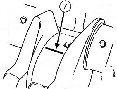
11. To establish without greasing of a cover of radical bearings.
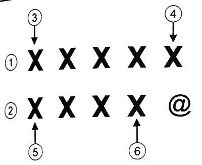
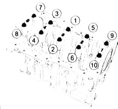
12. Tighten the old bolts of the main bearing caps in the sequence shown in the figure to a torque of 25 Nm, and then tighten another 47°± 5°.
13. To remove covers of radical bearings of a cranked shaft.
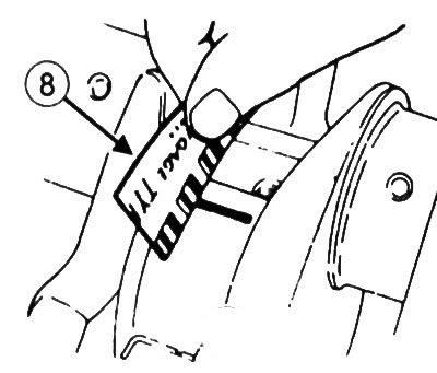
14. Measure the width of the most flattened part of the round probe using the scale on the package of the round probe (8). The gap value should be 0.028~0.054mm.
15. Remove the remnants of a round probe from the crankshaft main journals and main bearing caps.
16. With a micrometer, measure the thickness of each thrust half-ring of the crankshaft. The thickness should be 2.95 mm.
17. Apply oil to the crankshaft main bearing shells (only on surfaces in contact with the crankshaft).
18. Install thrust washers and crankshaft.
19. Install the main bearing caps.
20. Tighten the old main bearing cap bolts to the required torque.
21. Make sure that the crankshaft rotates easily and without jamming.
22. Install the dial gauge with support as shown.
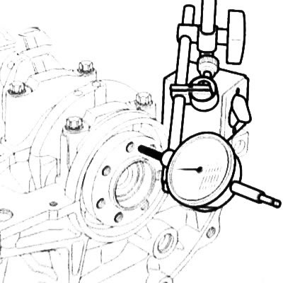
23. Place a dial indicator probe on the flywheel mounting surface on the crankshaft.
24. Rest the crankshaft against the thrust half ring by pushing it towards the dial gauge.
25. Reset the dial indicator.
26. Move the crankshaft in the opposite direction (from dial indicator).
27. Read the value of the crankshaft end play from the dial gauge.
Note:
Axial play of the crankshaft:
- without thrust half rings: 0.045~0.252mm;
- with thrust half rings: 0.045~0.852mm.