
Removal and installation of a camshaft, K7M engine (8 valves)
Note: The cylinder head must be removed to remove and install the camshaft.
Removing
1. Remove the cylinder head from the engine.
2. Place the cylinder head on a workbench.
3. Using the camshaft pulley lock (Mot. 799-01), unscrew the bolt (1) camshaft pulley.
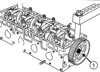
4. Remove the camshaft sprocket.
5. Turn away nuts and bolts of adjustment of a backlash in valves.
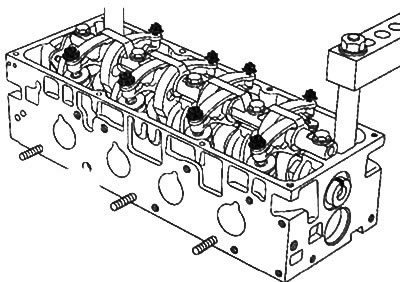
6. To turn away bolts of an axis of yokes and to remove it from a head of the block of cylinders.
7. Mark the installation position of each rocker arm.
8. Remove the bolts (2) from the camshaft flange.
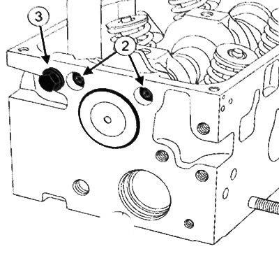
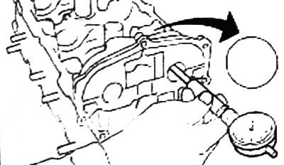
9. Pry off the camshaft end cap with a screwdriver and remove from the cylinder head.
Note: Bolt (W) serves to seal the hole (if available). The bolt must be installed to prevent engine oil leaks.
10. To take a camshaft from a head of the block of cylinders.
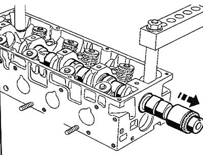
11.Remove the camshaft seal from the timing drive side.
Installation
Caution: Be sure to replace the camshaft end cap with a new one.
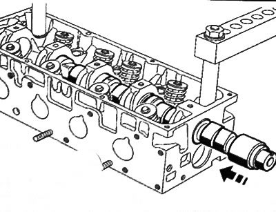
1. Insert the camshaft into the cylinder head.
2. Install bolts (4) camshaft flange.
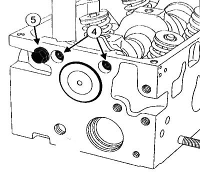
3. Tighten the camshaft flange bolts to 10 Nm.
Note: Bolt (5) serves to seal the hole (if available). The bolt must be installed to prevent engine oil leaks.
4. Apply a drop of high-strength fixing compound to the bolt (5) and screw it into the cylinder head.
5. Using a mandrel with a diameter of 43mm (Mot. 1488) Press a new end cap into the cylinder head from the flywheel side.
6. Press in a new camshaft seal (see below).
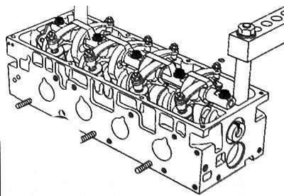
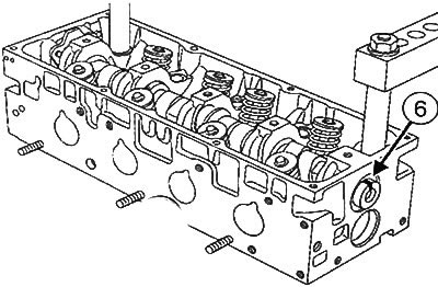
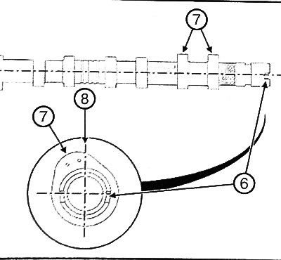
7. Turn the camshaft so that its groove (6) was facing up.
8. Install the axis of the rocker arms with a stamped mark (7) towards the timing gear.
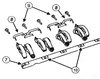
9. Install rocker stops in short sections (8) out.
Note: In some engine versions, the rocker shaft bolts are the same.
10. Place bolts (9) (size M8 x 100-28.7 mm) in holes (10)
11. Make sure the rocker arm adjustment screws do not touch the valves.
12. Tighten the rocker axle bolts to 23 Nm.
13. Lubricate the threads of the new camshaft sprocket bolt with oil.
14. Install the camshaft sprocket (11).
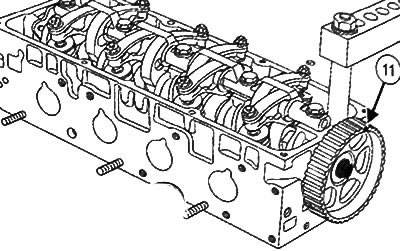
15. Tighten the camshaft pulley bolt to 45 Nm.
16. Install the cylinder head on the engine.
Check, K7M engine (8 valves)
Preparing for the test
Attention:
It is strictly forbidden to use the engine oil pan as a support. Its deformation can lead to engine failure:
- due to the overlap of the oil receiver,
- due to the rise of the oil level above the permissible level and engine runaway.
1. Drain the liquid from the engine cooling system.
2. Remove:
- cylinder head,
- camshaft.
3. Before performing any checks, you must:
- clean the camshaft with «Surface cleaner» and dry with «Pneumatic spray gun»,
- check that the surfaces of the camshafts are free of scratches, impact marks and excessive wear (if necessary, replace the camshaft).
Checking the radial clearance of the camshaft
1. Radial clearance (difference between the diameter of the camshaft bearing caps on the cylinder head on the camshaft) should be within 0.03 -0.08 mm.
Checking the diameters of the piston pins of the camshaft
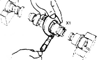
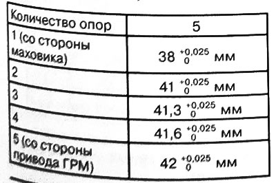
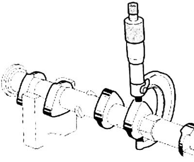
2. Using an external micrometer, measure the diameter (X1) camshaft journals, which must be within:
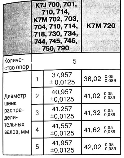
Note:
- Main bearing No. 1 is located on the flywheel side.
- Checking the inner diameter of the camshaft bearings in the cylinder head
3. Check the diameter of the holes of the camshaft bearings, which should be as follows:
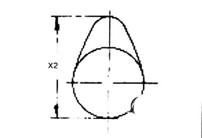
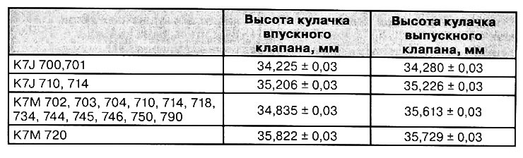
Checking the height of the camshafts
1. Place the camshaft on two lightly oiled v-blocks.
2. Using «External micrometer» measure the height of the cams (X2) which should be:
Checking the axial movement of the camshaft
1. Install:
- camshaft,
- camshaft flange
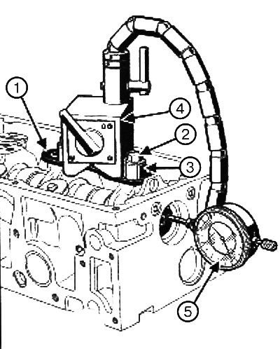
2. Install:
- metal plate (ex: fixture (Mot. 588)) (1), bolted rocker axles (2) on bearings No. 1 and No. 2 using spacers (3). Spacer dimensions:
- adaptation «indicator rack» (4) on a metal plate.
- «Indicator» (5) on the holder.
3. Install «Indicator» on the end of the camshaft.
4. Move the camshaft towards «indicator» all the way.
5. Set arrow «indicator» to zero.
6. Move the camshaft away from «indicator» all the way.
7. Check the axial clearance, which should be within 0.01 - 0.15 mm.
8. Remove:
- camshaft flange,
- camshaft
9. Install:
- camshaft,
- cylinder head.
10.Fill the cooling system with liquid and remove air from it.
Removal and installation of a camshaft, K4M engine (16 valves)
Removing
1. Place the vehicle on a two post lift.
2. Disconnect the battery.
3. Remove:
- right front wheel
- accessory drive belt,
- right pendulum suspension support,
- timing belt,
- silencer,
- air filter housing,
- throttle block,
- intake manifold,
- ignition coils,
- cylinder head cover.
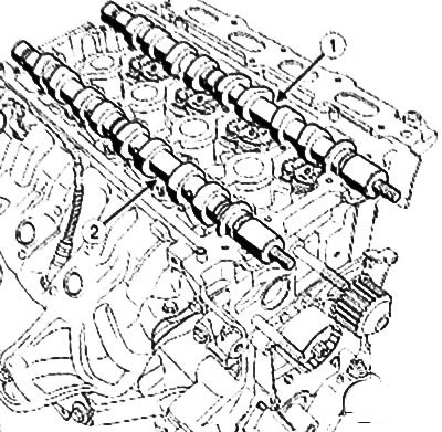
4. Remove:
- intake camshaft (1),
- exhaust camshaft (2).
Installation
Camshaft identification
Inlet camshaft
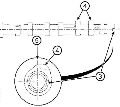
1. Position the groove (3) at the end of the camshaft horizontally and below the axis of the shaft.
cams (4) cylinder number 1 should be to the right of the vertical axis (5), when viewed from the flywheel side of the engine.
Exhaust camshaft
2. Position the groove (6) at the end of the camshaft horizontally and below the axis of the shaft.
cams (7) cylinder Ng 1 must be to the left of the vertical axis (8), when viewed from the flywheel side of the engine.
3. Install the camshafts by lubricating the bearing journals with engine oil.
4. Install:
- intake camshaft,
- exhaust camshaft.
Note: Be sure to replace the camshaft stud if it comes loose with the nut.
5. Install:
- cylinder head cover,
- ignition coils,
- intake manifold,
- throttle block,
- air filter housing,
- intake silencer,
- timing belt,
- right pendulum suspension support,
- accessory drive belt,
- right front wheel.
6. Connect the battery.