
Removal and installation of pistons with connecting rods
1. Place the vehicle on a two post lift.
2. Disconnect the negative battery terminal.
3. Remove the engine protection tray.
4. Drain the coolant from the engine cooling system.
5. Drain the engine oil from the engine.
6. Remove the implement drive belt.
7. Remove the crankshaft pulley.
8. Remove the timing belt.
9. Remove the air filter unit.
10. Remove rocker cover.
11. Remove the cylinder head from the engine (see above).
12. Remove the oil pan from the engine (see chapter "Lubrication system").
13. Remove the oil pump (see chapter "Lubrication system").
14. Mark the connecting rods and connecting rod caps relative to the engine cylinders with a marker (cylinder number 1 is located on the side of the flywheel).
Caution: Do not mark connecting rods and connecting rod caps with punches or engravings, as this may cause cracks. Use only marker.
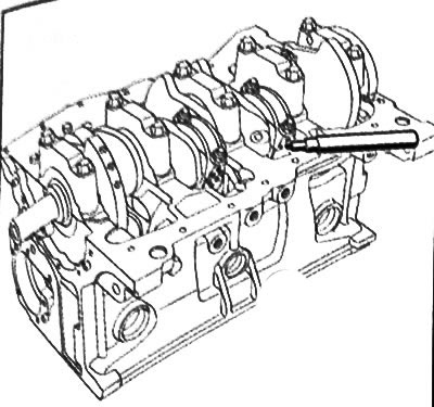
15. Unscrew the nuts of the connecting rod caps.
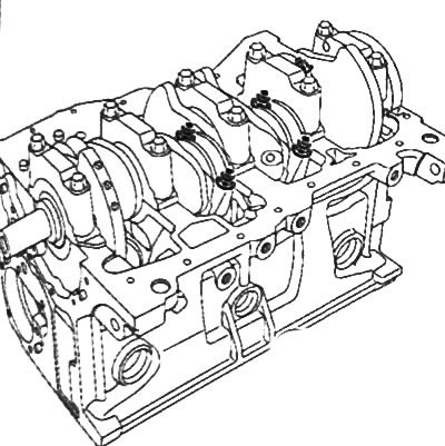
16. Remove the connecting rod caps and remove the connecting rod bearings, having previously marked their location relative to the caps.
Note: When performing work, use work gloves.
17. To take pistons with rods in gathering from a head of the block of cylinders.
18. Remove the upper connecting rod bearings by marking them with a marker relative to the connecting rods.
Disassembly of pistons with connecting rods
Note:
- Piston rings should only be removed when parts need to be replaced or the connecting rods or pistons need to be checked.
- Be careful not to damage the piston when removing the piston rings. Do not expand piston rings too wide as they may burst.
- If the chip is to be reused, mark the piston rings against the pistons.
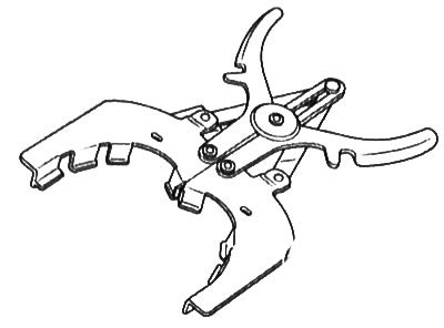
1. Using a special tool, remove the piston rings from the piston.
2. Place the piston on the base (1) piston pin replacement kit (Mot. 574-22).
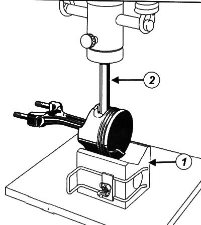
3. With the help of a press and a beard (2) remove the piston pin from the piston by aligning the piston pin with the hole in the base.
4. Disassemble all other pistons with connecting rods in the same way.
Note: On some versions, the piston pin is mounted in such a way that it can rotate freely in the piston and connecting rod. In this case, you just need to remove the retaining ring located under the mark "V" on the piston crown, and remove the piston pin from the piston and connecting rod.
Checking pistons and connecting rods
Preparing for the test
1. Place the vehicle on a two post lift.
2. Disconnect the negative battery terminal.
3. Remove pistons with connecting rods as an assembly.
4. Disconnect the connecting rods from the pistons.
5. Thoroughly clean parts before checking with cleaning agent and dry with compressed air.
6. Check that the parts are not named scratches, impact marks or abnormal wear (if defects are found, replace the part with a new one).
Pistons
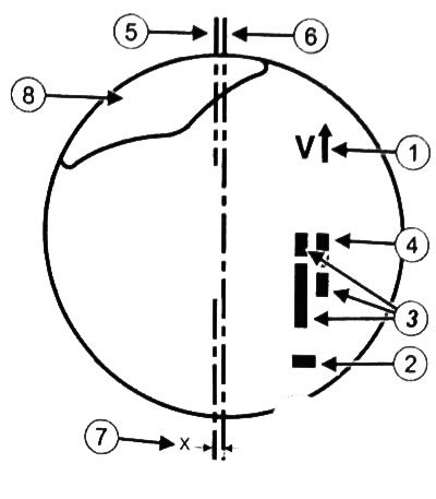
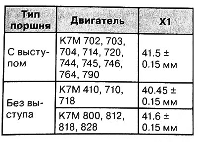
First model:
1. Piston installation direction (flywheel side arrow). 2. Piston class (A-B-C). 3. Used by supplier only. 4. Engine type. 5. The axis of the piston pin. 6. Axis of symmetry of the piston. 7. Displacement of the axis of the piston pin relative to the axis of symmetry of the piston (0.8+0.15mm). 8. Protrusion on the piston crown (except for engines K7M710, 410).
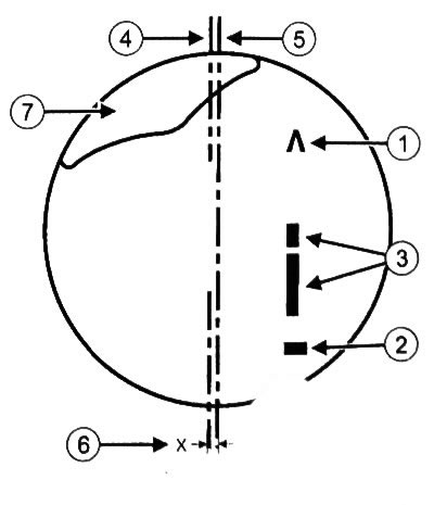
Second model:
1. Piston installation direction (flywheel side arrow). 2. Piston class (A-B-C). 3. Used by supplier only. 4. The axis of the piston pin. 5. Axis of symmetry of the piston. 6. Displacement of the axis of the piston pin relative to the axis of symmetry of the piston (0.810.15 mm). 7. Protrusion on the bottom of the piston (except for engines K7M 710, 410).
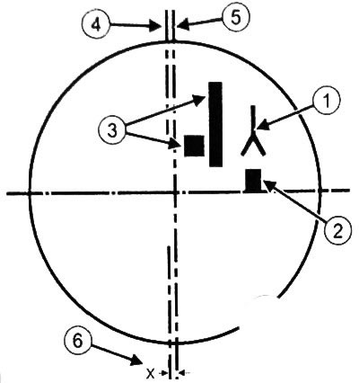
Third model:
1. Piston installation direction (flywheel side arrow). 2. Piston class (A-B-C). 3. Used by supplier only. 4. The axis of the piston pin. 5. Axis of symmetry of the piston. 6. Displacement of the axis of the piston pin relative to the axis of symmetry of the piston (0.8±0.15mm).
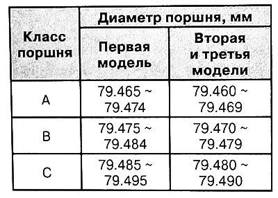
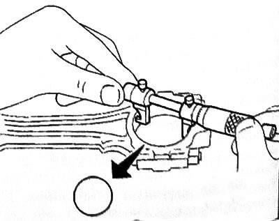
1. Measure the piston diameter with a micrometer (X1).
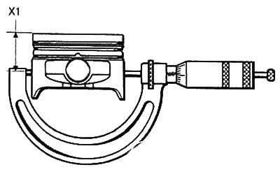
Note: Before checking, make sure that the piston pin rotates freely in the piston.
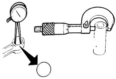
2. Use a caliper to measure the dimensions of the piston pin.
Outer diameter: 18.990—18.994 mm
Inner diameter: 10.7—11 mm
Length: 61.7-62mm
3. Measure the thickness of the piston rings with a micrometer.
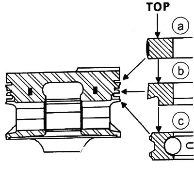
A. Top compression ring. b. Second compression ring With. Oil ring.
| Piston rings | Thickness, mm |
| Top compression ring | 1.478-1.49 |
| Second compression ring | 1.478-1.49 |
| Oil scraper ring | 2.5 |
4. Measure the backlash between the piston groove and the piston ring using a set of flat feeler gauges (9) (measure at three points around the circumference - through 120°).
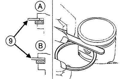
A.Incorrect position of the flat probe.IN.Correct position of the flat probe.
| Piston rings | Gap between piston groove and piston ring, mm |
| Top compression ring | 0.05-0.06 |
| Second compression ring | 0.04-0.052 |
| Oil scraper ring | 0.02-0.05 |
5. Place the piston ring (10) into the cylinder.
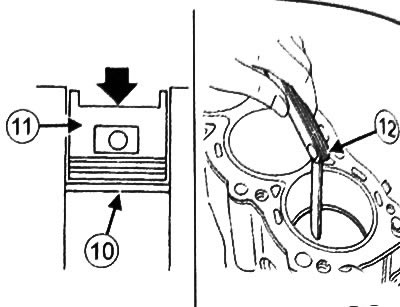
6. Piston (11) push the ring to the middle of the cylinder.
7. Measure the piston ring gap using a set of flat feeler gauges (12).
| Piston rings | Gap in the lock of the piston ring, mm |
| Top compression ring | 0.20-0.35 |
| Second compression ring | 0.40-0.60 |
| Oil scraper ring | 0.38-1.40 |
Connecting rods
Caution: Do not use sharp tools to mark the connecting rod caps as this may cause a crack to develop. Use a marker for marking.
Note: There is only one single connecting rod cap for each connecting rod. Do not replace or confuse connecting rod caps. Connecting rod caps must be marked before removal.
1. The maximum weight difference between pistons and connecting rod assemblies must not exceed 6 g.
2. The center distance between the upper and lower connecting rod heads is 128+0.035mm.
3. Install the connecting rod cover and tighten the connecting rod bolts and nuts to 43 Nm.
4. Using an inside gauge or caliper, measure the diameter of the hole in the bottom head of the connecting rod without connecting rod bearings. The diameter of the hole in the bottom head of the connecting rod should be 47.612-47.625 mm.
5. Using an inside gauge or caliper, measure the diameter of the hole in the upper head of the connecting rod. The diameter of the hole of the upper head of the connecting rod should be 18.953-18.966 mm.
6. Remove oil from the crankshaft journal and from the connecting rod bearings.
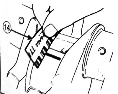
7. Place a piece of the round probe (calibrated wire) (13) parallel to the axis of the connecting rod journal of the crankshaft (do not place above the oil hole)
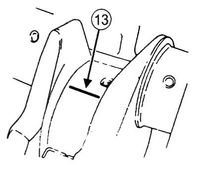
Note: Do not rotate the connecting rod or crankshaft while checking.
8. Install the connecting rod with piston assembly.
9. Remove the connecting rod with piston assembly.
10. Measure the width of the most flattened part of the round probe using the scale (14), printed on the packaging of the round dipstick. The gap should be 0.022-0.045 mm.
11. Remove the remnants of a round probe from the crankshaft journal and liners.
12. Install the piston with the connecting rod in the engine.
13. To place the piston with a rod of the corresponding cylinder in position of the bottom dead center.
14.Install the magnetic bracket on the oil pan mounting surface on the cylinder block.

15. Install the dial gauge on the magnetic bracket by placing its feeler gauge on the flat surface of the connecting rod cap.
16. Without applying excessive force, manually move the connecting rod from stop to stop.
17. Mark the maximum and minimum longitudinal movement of the connecting rod to determine the clearance between the connecting rod and the crankshaft.
| Engine | K7M |
| Longitudinal play of the connecting rod | 0.310—0.604 mm |
18. In the same way, check all other pistons with connecting rods.
Final operations
1. Install piston rings (if filmed).
2. Assemble pistons with connecting rods (if understood).
3. Install the pistons with connecting rods in the engine.
Assembly and installation of pistons with connecting rods
Caution: Be sure to replace the connecting rod bolts with new ones.
Note: Do not strike or distort the contact surfaces of the connecting rod cap and connecting rod to prevent damage.
Attention: When cleaning pistons with connecting rods, use goggles with side protection.
1. Clean pistons and connecting rods with cleaning agent.
2. Dry pistons and connecting rods with compressed air.
Note:
- The connecting rod bearings do not have any mounting tabs or grooves.
- Use the special tool to install the connecting rod bearings (Mot. 1492) and a set of adapters (Mot. 1492)
3. Select bearing shell support (3) for the corresponding engine version (engine type designation (4) marked on the base).
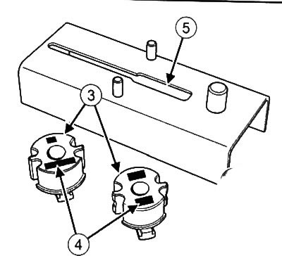
4. Slide the bearing shell support into the groove (5) bearing insert fittings (Mot. 1492).
5. Place the connecting rod on the tool base.
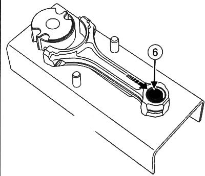
6. Make sure the bottom (6) the upper head of the connecting rod rests on the centering pin.
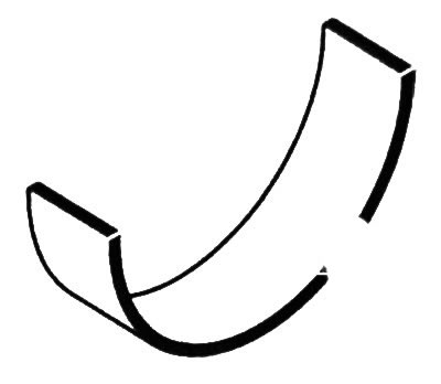
7. Place the bearing shell (7) on a support.
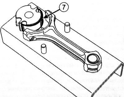
8. Push the bearing shell support (in the direction of the arrow), to fully insert the bushing into the connecting rod.
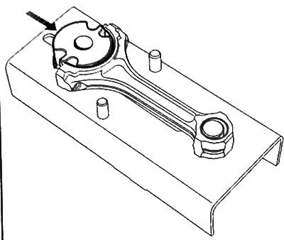
9. Remove the bearing shell support and repeat the operation for the remaining connecting rods.
10. Push the connecting rod cap into the pins (8) device bases.
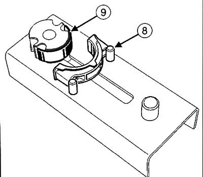
11. Place the bearing shell (9) on a support.
12. Push the bearing shell support (in the direction of the arrow), to fully insert the bushing into the connecting rod cap.
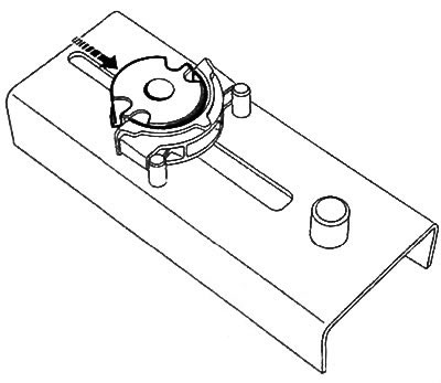
13. Remove the connecting rod cover from the fixture and install the liners in the rest of the connecting rod caps in the same way.
14. Visually check the condition of the connecting rods (bending and twisting).
15.Clean the contact surfaces between the connecting rod and the connecting rod cap.
16. Place the upper ends of the connecting rods on the electric stove, making sure that the bushings of the upper ends of the connecting rods are fully in contact with the surface of the plate.
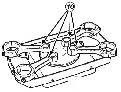
Note: To avoid overheating, place a piece of solder on each upper end of the connecting rods (10), whose melting point is approximately 250°.
17. Heat the upper ends of the connecting rods until the pieces of solder melt.
18.Check that the piston pins fit freely into the bores of the new pistons.
Note: Use dowel pin A19 (12) and centering tool C19 (13) from piston pin replacement kit (Mot. 574-22).
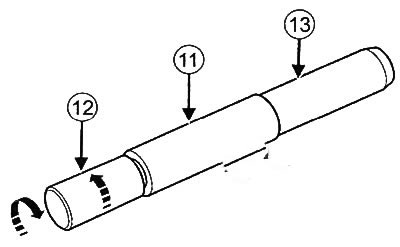
19. Insert piston pin (11) on the dowel pin (12).
20. Screw in the centering device (13) all the way.
21. Loosen the dowel pin (12) a quarter turn.
Attention: The connecting rods are symmetrical and can be installed in two directions. However, all connecting rods must be installed in the same direction.
Note: K7M 710, 410 engines do not have protrusions on the piston bottoms. You need to navigate only along the engraved arrow on the piston bottom.
22. Select the direction of installation of pistons and connecting rods.
First installation direction:
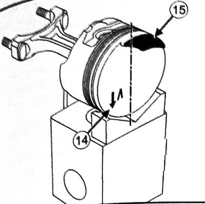
Cylinders 1-2:
- Place an arrow (14), engraved on the piston crown, so that it is located above and to the right of the vertical axis, and the protrusion (15) - below and to the left of the vertical axis.
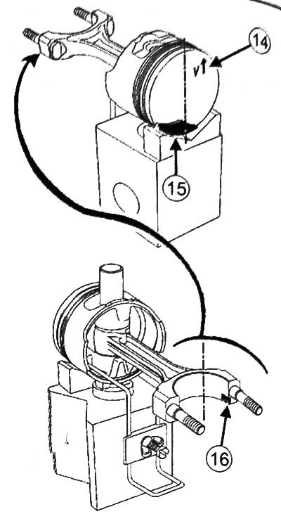
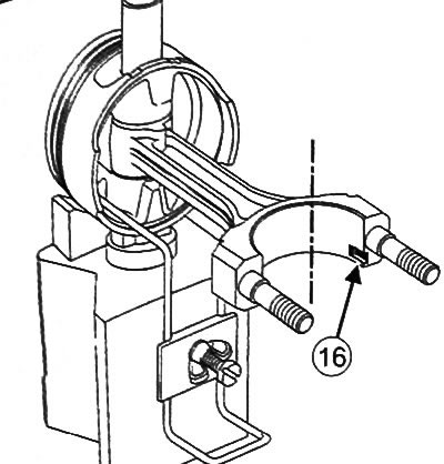
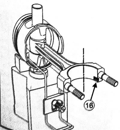
- Retainer groove (16) connecting rod should be located below and to the right of the vertical axis.
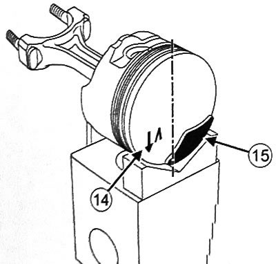
Cylinders 3-4:
- Place an arrow (14), engraved on the piston crown, so that it is located above and to the right of the vertical axis, and the protrusion (15) - above and to the left of the vertical axis.
- Retainer groove (16) connecting rod should be located below and to the right of the vertical axis.
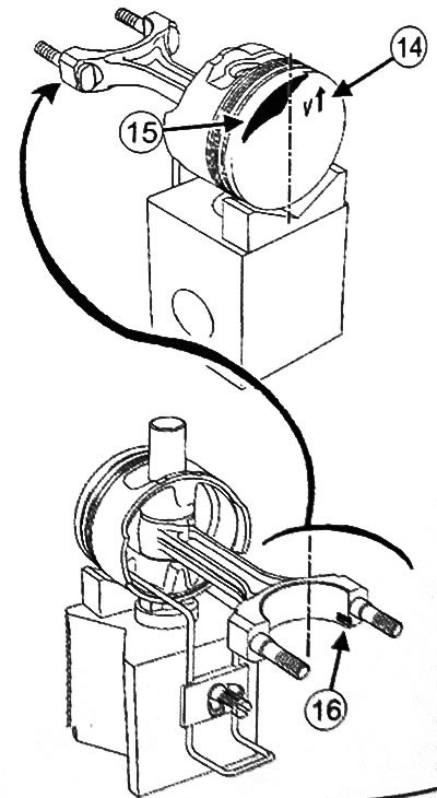
Second installation direction:
- Place an arrow (14), engraved on the piston crown, so that it is located below and to the left of the vertical axis, and the protrusion (15) above and to the right of the vertical axis.
- Retainer groove (16) connecting rod should be located below and to the right of the vertical axis.
Cylinders 3-4:
- Place an arrow (14), engraved on the piston crown, so that it is located below and to the left of the vertical axis, and the protrusion (15) -below and to the right of the vertical axis.
- Retainer groove (16) connecting rod should be located below and to the right of the vertical axis.
Versions without retainer groove in connecting rod
- Place an arrow (14), engraved on the piston crown below and to the right of the vertical axis.

- Connecting rod mark (16) should be located to the left of the vertical axis.
23. Place the piston with connecting rod on the fixture:
Pistons with old markings:
- Place ring B18 on the base of the tool (17) with V-piece V18 (18), and, firmly pressing the piston to the ring (at a right angle), fix the entire assembly with a clamp (19).
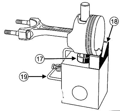
- Make sure the piston pin holes line up with the B18 ring.
Pistons with new markings:
- Depending on the version, place a B10 ring or a B18 ring with V18 on the base (Mot. 574-23) (K7M engine) on the ground (20), after which, firmly pressing the piston to the ring (at a right angle), fix the entire assembly with a clamp (21).
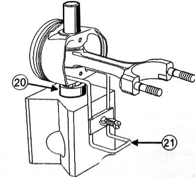
- Make sure the piston pin holes line up with the B18 ring.
24.Lubricate centering device and piston pin with engine oil.
25. Insert the piston pin into the assembly to make sure it enters freely. If not, reposition the piston.
Note: The following operation must be carried out as quickly as possible to avoid premature cooling of the connecting rod.
Caution: Wear gloves to avoid burns.
26. After sufficient heating of the connecting rods (pieces of solder on them should melt), remove the solder from the connecting rod and insert the guide into the connecting rod, and then insert the connecting rod into the piston on the special tool.
27. Quickly press in the piston pin so that the guide from the connecting rod reaches the edge of the base of the tool.
28.Check that the piston pin does not protrude beyond the edges of the piston skirt.
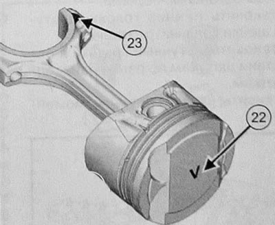
Note:
Version with floating piston pin:
- Insert the circlip into the piston by turning it±45°relative to the groove.
- Lubricate it with engine oil and manually insert it into the piston, then fix it with a second retaining ring.
- Turn the second circlip around the groove by±45°.
- Arrow on the bottom of the piston (22) should be directed downwards, and the influx (23) the connecting rod must be on top.
29.Clean the grooves in the piston.
thirty. Install the piston rings in their places, paying attention to the mark "TOR" on the surface of the piston rings was directed upwards.
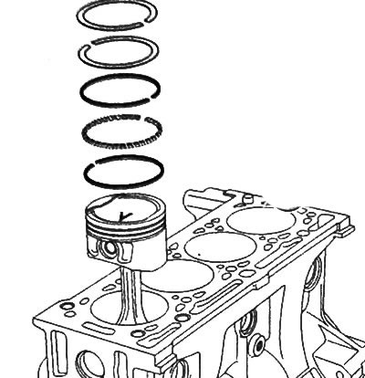
Note: Position the piston ring locks at different angles to each other as shown in the illustration.
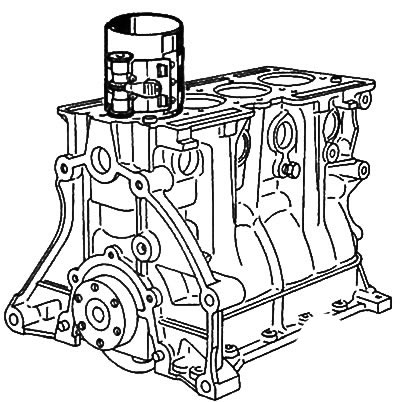
31. Lubricate the piston with engine oil and compress the piston rings with a tool for installing pistons in the engine cylinders.
32. Lubricate the engine cylinders and crankshaft connecting rod journals with engine oil.
33.Install the piston and connecting rod assembly and check that the piston number matches the engine cylinder number (Cylinder #1 is on the flywheel side), and also that all the installation marks on the piston crown are located correctly (The arrow on the bottom must point towards the flywheel).
34. Install the rest of the pistons in the same way.
35.Install the connecting rod ends onto the crankshaft journals.
36.Install the connecting rod caps according to the previously marked marks on the connecting rods.
37. Tighten the connecting rod nuts to 10 Nm.
38. Tighten the connecting rod nuts to 43 Nm.
39. Make sure that the crankshaft rotates freely and without wedging.
40. Tighten the connecting rod bolts to 25 Nm, then tighten another 45+5°.
41. Tighten the connecting rod bolts another 110+2°.
42. Install oil pump (see chapter "Lubrication system").
43. Install oil pan (see chapter "Lubrication system").
44. Install the cylinder head.
45. Install rocker cover.
46. Install the air filter unit.
47. Install the timing belt.
48. Install the crankshaft pulley.
49. Install the attachment drive belt.
50. Fill the engine with engine oil.
51. Fill the cooling system.
52. Connect the battery.
53. Bleed the cooling system.
54. Check for leaks.
55. Install the engine protection tray.