
Do the following:
- install the cylinder block on the workbench crankcase up;
- install the piston of the first cylinder (flywheel side) to the NMT position;
- paint a mark on the connecting rod and its cap (in the absence of numbering) for proper installation during assembly;
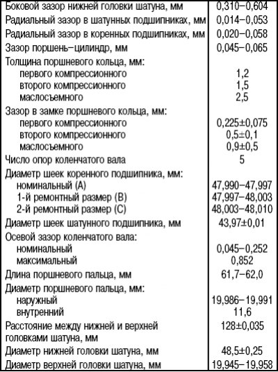
Pic. 3.53. Measuring the backlash of the bottom cap of the connecting rod
- use a feeler gauge to check the bottom end clearance of the connecting rod (pic. 3.53) and compare the result with the dimensions given in Table. 3.3;
Table 3.3. Technical data of the crankshaft and parts of the connecting rod and piston group
- unscrew the nuts securing the lower connecting rod cover and remove the cover together with the insert. Attach the insert with adhesive tape to the storage lid. Reusing the inserts is not recommended, but if they are to be used again, they should be reinstalled;
- put plastic tubes on the connecting rod cap bolts or wrap them with adhesive tape to prevent damage to the cylinder surface when removing the piston from the block;
- inspect the top of the cylinder mirror. If there is a significant ledge there, it must be removed, since the piston and its rings can be damaged during removal;
- paint numbers on the bottoms of all pistons;
- Carefully remove the piston through the top of the cylinder block by pressing down on the piston head with a suitable wooden rod. Once the piston and connecting rod have been removed, remove the upper bearing shell and tape it to the connecting rod for storage;
- turning the crankshaft half a turn, remove the pistons and connecting rods of the remaining cylinders in the same way. Before removing parts, mark them (or make sure you have it);
Attention! The piston pins are pressed tightly into the upper ends of the connecting rods and have a floating fit in the piston bosses. Retaining rings are not used.
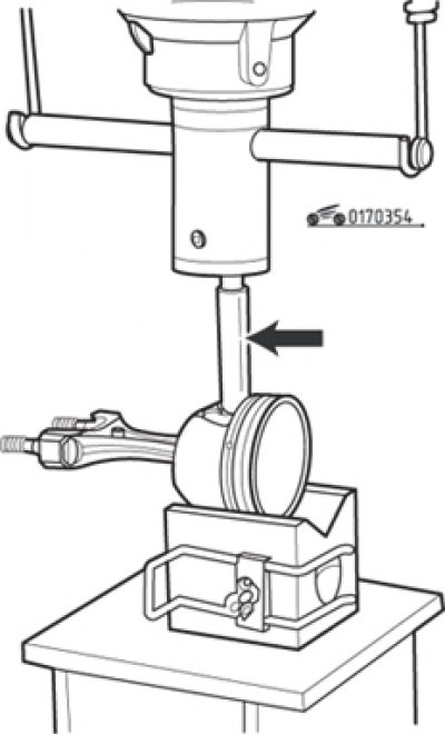
Pic. 3.54. Removing the piston pin from the piston using a mandrel (arrow)
- install the piston in the V-shaped stand so that the piston pin aligns with the hole to remove it (pic. 3.54);
- using a piston pin extractor, remove it from the piston using a press.
Inspection
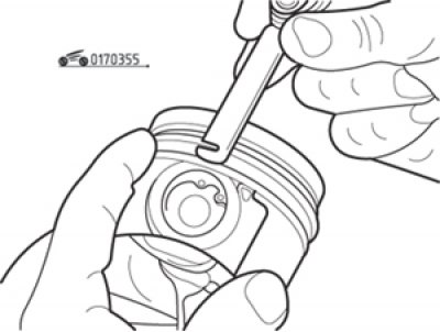
Pic. 3.55. Removing piston rings with a feeler gauge
Clean the pistons and connecting rods from dirt and carbon deposits. Using two or three flat feeler gauges, remove the rings from the pistons up (towards the bottom of the piston) (pic. 3.55). Remove carbon from the piston crown with an aluminum scraper. Do not use sandpaper for this purpose, as the grains of the abrasive are embedded in the aluminum of the piston and subsequently cause scratches. Remove carbon deposits from the piston grooves using a suitable piece of piston ring, being careful not to scratch the groove surface.
Wash the pistons from the removed deposits. Make sure that the holes in the oil scraper grooves are not clogged with dirt.
Inspect the friction surfaces of the pistons. Permissible is wear in the form of vertical «bald patches» on the pressure-receiving surface of the piston skirt and a small gap in the fit of the upper compression ring in the groove. Scoring and scratches on the piston skirt may indicate that the engine has been overheated for any reason: poor cooling, lubrication, too high combustion temperature. Burn marks on the skirt are a sign of gas leakage from the combustion chamber, possibly caused by wear on the cylinder walls or piston rings. Burn marks or pitting on the piston crown are usually signs of an engine running with detonation caused by pre-ignition or low-quality gasoline. For the same reason, in some cases, the piston head may be melted. Re-leaning the mixture due to air leakage at the inlet can also cause the piston to overheat.
All causes of the listed damage must be eliminated before the engine is put into operation, otherwise similar damage to the piston group will occur again.
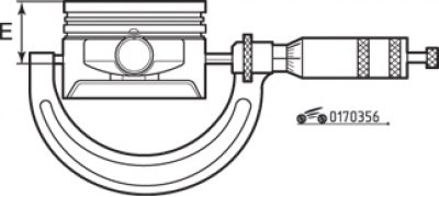
Pic. 3.56. Measuring the piston diameter with a micrometer: E= (42±0,01) mm
Using a micrometer, measure the diameters of all four pistons at a distance (42±0,01) mm from piston crown (pic. 3.56) perpendicular to the axis of the piston pin. Compare results of measurements with specified in tab. 3.4.
Table 3.4. The dependence of the piston diameter on the cylinder diameter
If the piston diameter is out of tolerance, replace the entire piston kit. It should be borne in mind that the cylinder block may have been bored out during a previous overhaul, and oversized pistons may have been installed accordingly. Record the measurement results and use them to check the clearances later when the cylinder diameters are measured.
Measure the gaps between the piston rings and the piston grooves, to do this, install the rings in the grooves and, using a set of flat feelers, take the appropriate measurements in three or four places in each groove. The measured dimensions must not exceed 0.1 mm, otherwise the pistons will need to be replaced.
Carefully inspect the connecting rods, pins, and connecting rod caps for wear, cracks, or other surface damage. Visually check the following:
- condition of connecting rods (they can be twisted or bent);
- density of fit of bearing caps on connecting rods (if necessary, use an emery board to remove burrs to ensure that the caps fit properly).
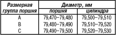
Pic. 3.57. Piston ring gap measurement
Before putting the rings on the pistons, install them one by one in your cylinder and check the gap in the ring lock. Push the ring into the cylinder with the piston so that the plane of the ring is parallel to the top plane of the block (pic. 3.57). Compare the measurement results with those given in Table. 3.3.
Assembly
Assembly order:
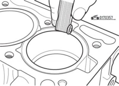
Pic. 3.58. Piston ring profiles
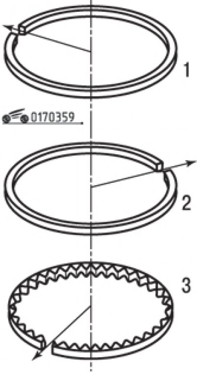
Pic. 3.59. The location of the locks of the piston rings at an angle of 120°relative to each other
- install rings on the pistons - put them on through the piston crown, starting with the oil scraper ring and using the same flat feeler gauges that were used when removing the rings. Piston ring profiles are shown in fig. 3.58. Compression rings are installed with the inscription «TOR» up. They are very fragile, so be careful when installing. Spread the piston ring locks at an angle of 120°relative to each other (pic. 3.59);
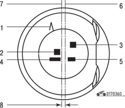
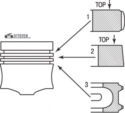
Pic. 3.60. Piston marking: 1 - the direction of installation of the piston label «L» towards the flywheel 2, 4, 5 - supplier's marking; 3 - piston size group (A–B–C); 6 - axis of symmetry of the piston; 7 - the axis of the hole for the piston pin; 8 - axis offset (7) holes for the piston pin relative to the plane of symmetry (6) piston is 0.9mm
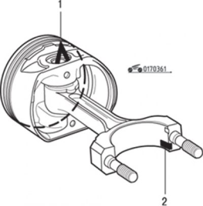
Pic. 3.61. The position of the connecting rod relative to the piston: label «L» (1) on the piston crown must be at the top, and the locking lug of the bearing shell (2) bottom end of the connecting rod - below
Pic. 3.62. Heating on the electric stove of the upper heads of the connecting rods: a - a piece of tin solder
- assemble the piston with the connecting rod. Label «L» on the bottom of the piston (pic. 3.60) should be directed towards the flywheel, and the locking lug of the bearing shell of the lower head of the connecting rod should be, as shown in fig. 3.61. Place the top end of the connecting rods on a 1500W hot plate as shown in fig. 3.62. To control the heating temperature of the connecting rods, place a small piece of tin solder with a melting point of approximately 250°C on the top head of each connecting rod in area a;
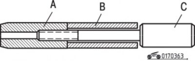
Pic. 3.63. Piston pin installation (IN) on the mounting rod (WITH) and connection with centering device (A)
- prepare the piston pins. Make sure they fit freely into their respective pistons. Install the piston pin on the locating rod, screw in the centering tool until it stops and then unscrew it 1/4 turn (pic. 3.63);
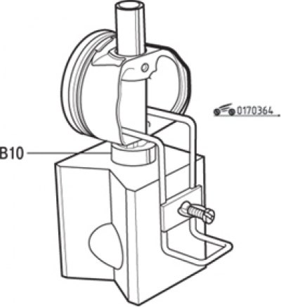
Pic. 3.64. Fitting the piston to the connecting rod assembly tool: B 10 - sleeve-limiter
- install the piston on the stand, orienting it as shown in fig. 3.61. Between the piston and the stand, place a sleeve that limits the movement of the centering device when pressing the piston pin (pic. 3.64);
- lubricate the centering device and piston pin with engine oil;
Attention! Subsequent operations must be carried out as quickly as possible to avoid cooling the connecting rod.
- when the solder temperature reaches the melting point (solder will turn into a drop), wipe off a drop of solder;
- insert the connecting rod into the piston;
- as quickly as possible, insert the piston pin until the stop of the centering device into the stand;
- remove the centering device from the pin;
- make sure that the piston pin at any position of the connecting rod does not go beyond the boundaries of the piston bosses.