
Increased oil consumption indicates wear on the piston rings, valve guides and oil seals. You should make sure that leaks are not the cause of increased oil consumption, and only then draw a conclusion about the unsuitability of the piston rings and valve guides. To determine the probable cause of the malfunction, measure the compression in the engine cylinders. Also carry out tests using a vacuum gauge and determine the nature of the readings from this device.
Check the oil pressure with a pressure gauge. screwed into place of the oil pressure sensor, and compare the test result with the standard value. If the oil pressure is low, the cause may be worn main and connecting rod bearings or oil pump parts.
Loss of power, failures in engine operation, detonation or metallic knocks, increased noise from the gas distribution mechanism, increased fuel consumption indicate the need for a major overhaul, especially if all these signs of abnormal operation appear simultaneously. If all adjustments do not lead to improvement, then the only remedy for abnormal engine operation is a major overhaul. Overhaul consists of restoring engine parts to the condition specified in the technical data for a new engine.
During an engine overhaul, such units as the starter, generator and ignition distributor are also repaired. As a result, the repaired engine must have the qualities of a new unit and withstand significant mileage without failures.
Before starting an engine overhaul, read the description of the relevant procedures to get an impression of the upcoming scope of work and the requirements for them. If you follow all the rules and regulations, and if you have all the necessary tools and equipment, major repairs are not difficult to carry out, but they will require a significant investment of time.
Disassembly
- This operation is carried out after removing the power unit from the vehicle and disconnecting the gearbox from the engine.
Attention. When disassembling the engine, make sure that all parts can subsequently be installed in their original places.
- Before disassembling, remove all attachments from the engine, such as the generator, manifolds, pipes, clutch and make sure that the engine oil is drained from the engine.
- During disassembly, it is very important to maintain cleanliness to prevent contamination of the disassembled components.
- Before disassembling, clean the outside of the engine with kerosene or. if the engine is very dirty, use solvent.
- When the parts are removed from the engine, wash them in kerosene.
- Never immerse parts that have internal lubrication channels in kerosene. Such parts should be thoroughly wiped with a cloth soaked in kerosene. The lubrication channels must be cleaned with a wire rope.
- If possible, mount the engine on a stand; otherwise, mount the engine in such a way that it will not be damaged when loosening tight nuts and bolts.
- Disconnect the tube from the water pump and remove the guide tube for the oil level dipstick.
- Remove the cylinder head.
- Using a special device, the dimensions of which are shown in Figure 1.63, remove the toothed belt drive pulley from the crankshaft.
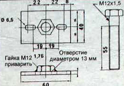
Pic. 1.63. Dimensions of the tool for removing the timing belt drive pulley from the crankshaft
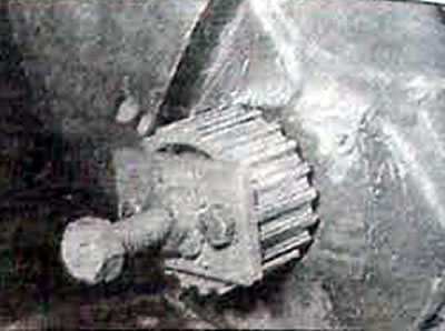
Pic. 1.64. Removing the timing belt drive pulley from the crankshaft
- Remove the lower inner timing belt guard.
- Remove the bolts and remove the front cylinder block cover with the crankshaft oil seal.
- Remove the clutch cover with pressure plate and the driven disc.
- Remove the flywheel.
- Remove the bolts and remove the oil sump and oil pump.
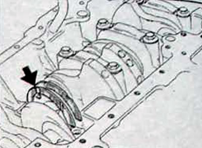
- Unscrew the bolt and remove the pulley from the intermediate or driven shaft, using an old timing belt or Mot 855 tool to keep the pulley from turning
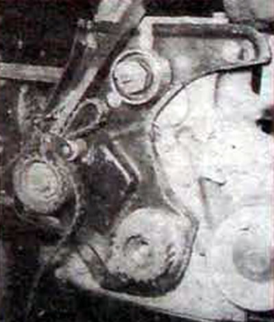
Pic. 1.65. Using tool Mot. 855 to keep the timing belt pulley from turning
Engine F3R 728
- Remove the bolts and remove the intermediate shaft cover with the oil seal.
- Unscrew the bolts and remove the lock plate securing the intermediate shaft
- Unscrew the bolts securing the plug that blocks access to the oil pump drive gear, remove the plug and remove the gear (pic. 1.67).
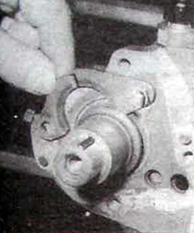
Pic. 1.66. Removing the lock plate securing the intermediate shaft cover on the F3R 728 engine
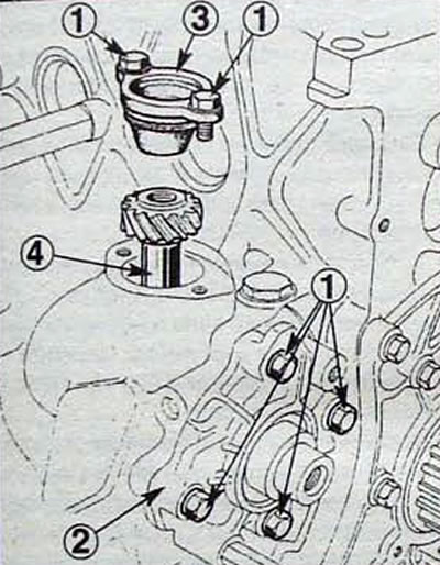
Pic. 1.67. Removing the oil pump drive gear on the F3R 728 engine: 1 - bolt; 2 - cover with oil seal; 3 - plug; 4 - oil pump drive gear
All engines
- Remove the timing belt tensioner roller.
- Check for identification marks on the connecting rod bottom cap and connecting rod for proper reassembly.
- If necessary, mark the position of the connecting rod bottom cap and connecting rod
- Unscrew the bolts securing the lower connecting rod covers and remove the covers along with the liners.
- Remove the connecting rod bearing shells and position them as follows. so that when assembling the engine they can be installed in their original places.
- Unscrew the bolts securing the main bearing caps and remove the caps along with the liners.
- Remove the main bearing shells and thrust washers and position them as follows. so that when assembling the engine they can be installed in their original places.
- Remove the crankshaft.
- Remove the pistons with connecting rods from the cylinder block.
- From the cylinder block side, remove the main bearing shells.
- After disassembling the engine and cleaning all its parts from dirt and oil, they should be checked for signs of wear. In cases where there are no established wear limits on the part. it is necessary to decide whether this part should be replaced with a new one or whether it is suitable for further use. When making a decision, factors such as the expected service life of the engine, the required degree of reliability of the part and the amount of disassembly and assembly work that will be required in the future when replacing it are taken into account.
Testing and assembly
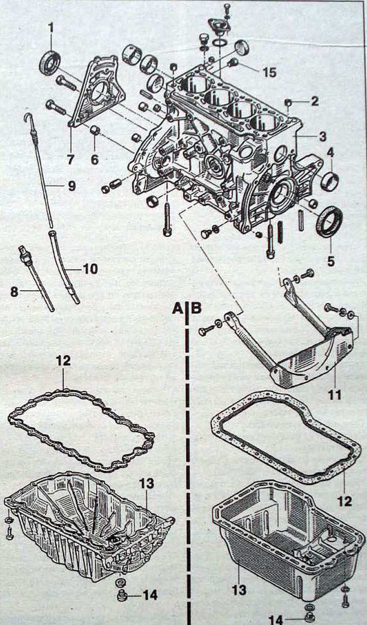
Pic. 1.68. Cylinder block: A - oil pan of the F3R 768 engine; B - oil pan of the F3R 728 engine; 1 - oil seal; 2 - centering sleeve; 3 - cylinder block; 4 - plug; 5 - oil seal; 6 - centering sleeve of the front cover; 7 - front cover of the cylinder block with oil seal; 8 - engine oil level/temperature sensor; 9 - dipstick for measuring oil level; 10 - guide tube for the dipstick for measuring the oil level; 11 - bracket; 12 - oil pan gasket; 13 - oil pan; 14 - engine oil drain plug; 15 - coolant drain plug
Attention! The pistons are supplied together with the cylinder block, as they are matched in pairs with the cylinder diameters. Cylinder diameters are divided into three classes, with the cylinder class being marked by a 5mm diameter drill hole on the exhaust manifold side of the cylinder block face (pic. 1.69).
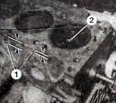
Pic. 1.69. Cylinder diameter marking on the cylinder block: 1 - drillings located in two different places; 2 - number on the piston bottom
- To achieve maximum engine life after a major overhaul with a minimum of problems, it is necessary not only to assemble all the parts correctly, but all parts and components must be spotlessly clean, all lubrication channels must be clean. The lock washers and spring washers are in place. Bearings and other parts with sliding surfaces must be thoroughly lubricated during assembly.
- Before starting assembly, replace any bolts, studs or nuts that have damaged threads with new ones. Should also be replaced» for new spring washers.
- Keep an eye on this during installation. so that the parts are installed in their original places. Also check the installation direction of the parts.
- Install the engine oil dipstick guide tube and water pump tube after applying Loctite to the sealing surfaces «Scelbloc».
- Wipe the outer parts of the main bearing shells and their installation locations in the cylinder block. Insert the upper main bearing shells into the cylinder block without lubrication. Please note that the top liners have grooves (pic. 1.70).
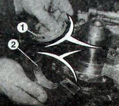
Pic. 1.70. Installing main bearing shells: 1 - the liner on the side of the cylinder block has a groove; 2 - the liner on the side of the lid does not have a groove
- Install the thrust half-rings for adjusting the axial play of the crankshaft, with the grooves located on the crankshaft side (pic. 1.71).
Pic. 1.71. Installation of thrust bearings and crankshaft end play adjustment rings
- Lubricate the working surfaces of the main bearings with clean engine oil and install the crankshaft into the cylinder block.
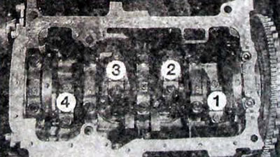
Pic. 1.72. The markings of the main bearing caps must be read from the side of the intermediate shaft or the idler roller of the toothed belt. The numbers indicate the cylinder numbers
- Install the caps with the main bearing shells No. 3, 4 and 5 on the intermediate shaft side and secure with bolts. tightening them to the required torque
- Make sure the crankshaft rotates easily and freely.
- Install the dial indicator on the magnetic stand and check the axial play of the crankshaft, which should be 0.070-0.230 mm (Fig 1.73). If the play differs from the required one, install thrust half-rings of a different thickness.
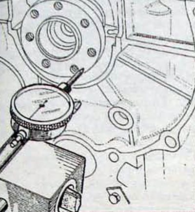
Pic. 1.73. Using a Dial Indicator to Measure Crankshaft Endplay
- Install the main bearing cap No. 2 and secure with bolts, tightening them to the required torque
- Install the No. 1 main bearing cap. Sealing is carried out on the sides of the lid.
- Clean the mating surfaces of the main bearing cap No. 1 and the cylinder block.
- Install the No. 1 main bearing cap without the gasket.
- Use the drill shank to measure the distance (C, fig. 1.74): If the distance is equal to or less than 5mm, choose a 5.1mm thick spacer; if the distance is more than 5 mm, select a 5.4 mm thick spacer.
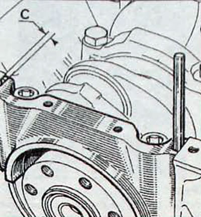
Pic. 1.74. Place (WITH) measuring the groove to select the thickness of the sealing gasket of the main bearing cap No. 1
- Remove the main bearing cover No. 1 and insert two gaskets of a certain thickness into the grooves of the cover, orienting them towards the outside, while the protrusion of the gaskets should not exceed 0.2 mm.
- Using two M10x1.5 studs, center and install the main bearing cap No. 1 with gaskets (pic. 1.75). Before installing the cover, lubricate the two gaskets and apply a thin layer of CAF 4/60 Thixo sealant to the bottom sealing surface (IN) covers.
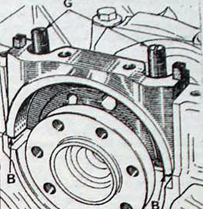
Pic. 1.75. Centering the #1 main bearing cap using two studs (G) and place (IN) applying sealant CAF 4/60 Thixo
- Remove the studs and screws that secure the No. 1 main bearing cap and use a clean, lint-free rag to wipe off excess sealant from the sides of the caps.
- Trim the protruding edges of the two spacers
- Lubricate the working edge of the crankshaft rear sealing ring with clean engine oil and install it into the cylinder block using a special tool
- Install the flywheel. Apply Loctite to the threads of the flywheel mounting bolts «Frenetanch». prevent the bolts from unscrewing, and tighten the flywheel mounting bolts.
- With the Mot. 582 block the flywheel from turning and tighten the flywheel mounting bolts to the required torque
- When assembling the piston with connecting rod, it is necessary. so that the pins on the lower end of the connecting rod are located on the side opposite to the arrow engraved on the bottom of the piston (pic. 1.76).
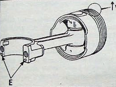
Pic. 1.76. Connecting rod and piston assembly. Arrow (V) engraved on the piston crown should be located on the side opposite the pins (E) on the lower end of the connecting rod
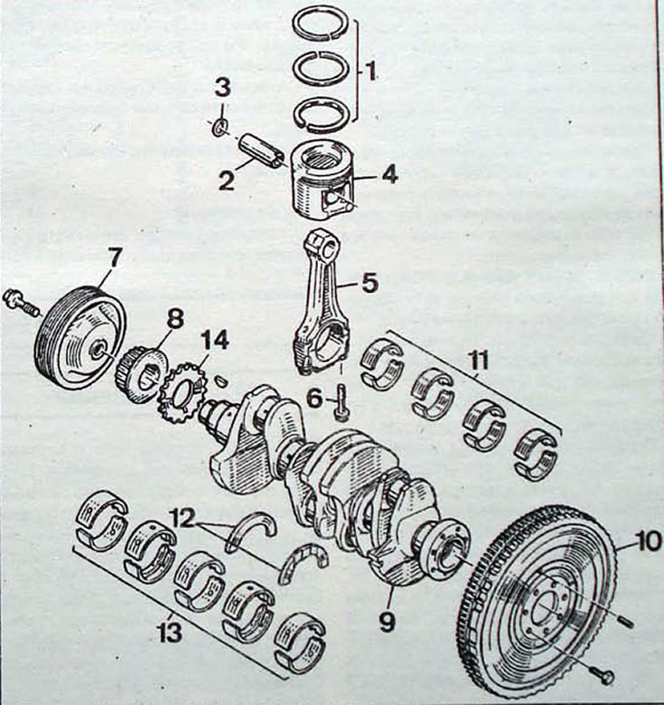
Pic. 1.77. Crankshaft, piston and connecting rod: 1 - piston rings; 2 - piston pin; 3 - retaining ring; 4 - piston; 5 - connecting rod; 6 - bolt securing the bottom cover of the connecting rod; 7 - crankshaft pulley for attachment belt drive; 8 - crankshaft pulley for timing belt drive; 9 - crankshaft; 10 - flywheel; 11 - connecting rod bearing shells; 12 - thrust half-rings that limit the axial movement of the crankshaft; 13 - main bearing shells; 14 - oil pump drive sprocket (engine F3R 768)
- Lubricate the piston pins with clean engine oil and install them into the piston and connecting rod. Secure the piston pins with retaining rings.
- Using special pliers, install the piston rings on the piston in the following sequence:
- oil scraper ring;
- lower compression ring;
- upper compression ring.
- When installed correctly, the piston rings should move freely in their grooves and the piston ring locks should be at a 120°angle and not in line with the piston pin axis.
- If rings are installed on the piston. which stood before, then they need to be installed in their original places.
- Lubricate the piston and piston rings with engine oil. Install the universal piston ring compressor and prepare to install the piston into the cylinder liner.
- Install the piston from the top side of the cylinder by carefully but firmly tapping the piston with the handle of a hammer to install the piston into the cylinder liner. When installing the pistons, make sure that the arrow on the piston bottom is directed towards the flywheel (pic. 1.78).
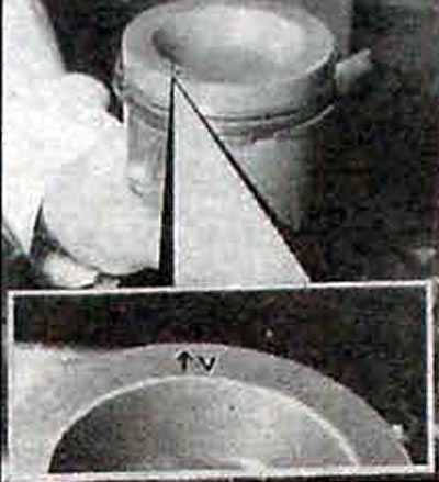
Pic. 1.78. Installing the piston into the cylinder, with arrow (V) on the piston bottom should be on the flywheel side
- Lubricate the working surfaces of the lower connecting rod bearings, install the connecting rod caps on the connecting rods and secure with bolts.
- Make sure the crankshaft rotates freely.
- Check the condition of the oil pump and the presence of a centering socket on the pump shaft of the F3R 728 engine.
- Install the oil pump and oil pan with a new gasket.
Engine F3R 728
- Lubricate and install the intermediate shaft.
- Install the oil pump drive gear into the cylinder block socket. Install the plug and secure it with two bolts.
- Insert the intermediate shaft fixing plate into the intermediate shaft groove and secure with bolts. Check that the shaft rotates freely and without jamming.
- Using a mandrel of the appropriate diameter, install the intermediate shaft oil seal.
- Install the front cover with a new oil seal.
All engines
- Install the pulley onto the intermediate shaft or idler pulley and secure with the bolt, tightening it to the required torque
- Using a mandrel of the appropriate diameter, install the crankshaft rear oil seal
- Check the presence of bushings in the cylinder block centering the front cover of the cylinder block.
- Apply a thin layer of CAF 4/60 Thixo sealant to the mating surface of the front cylinder block cover, install it on the cylinder block and secure with bolts.
- Install the lower inner timing belt guard.
- Install the tension roller and timing belt drive pulley to the crankshaft
- Install the cylinder head and timing belt.
- Install the water pump with a new gasket.
- Install the attachment drive pulley onto the crankshaft and secure with a bolt.
- Install the previously removed attachments onto the engine, and use new gaskets when installing the manifolds.
- Install a new oil filter.
- Install the driven disc and clutch housing with the pressure plate and secure with bolts, tightening them to the required torque.
- Install the engine into the car and fill with operating fluids.