
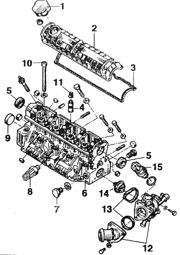
Pic. 1.41. Cylinder head: 1 - oil filler cap; 2 - cylinder head cover; 3 - cylinder head cover seal; 4 - valve guide; 5 - ring; 6 - cylinder head; 7 - plug; 8 - knock sensor; 9 - plug; 10 - cylinder head mounting bolt: 11 - oil seal cap; 12 - thermostat mounting elements; 13 - seals; 14 - thermostat; 15 - coolant temperature sensor
Removal
- To remove the cylinder head of the F3R engine, the power unit must be removed.
- Remove the power unit.
- Unscrew the two bolts (1, fig. 1.42) and loosen the bolt (2) ignition coil bracket and push the bracket down.
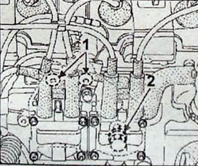
Pic. 1.42. Bolt Location (1 and 2) ignition coil bracket mounting
- Remove the timing belt.
- Remove the spark plug caps (pic. 1.43).
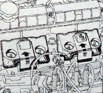
Pic. 1.43. Direction for removing spark plug caps
- Disconnect the connector from the knock sensor.
- Remove the cylinder detection sensor.
- Remove the absolute pressure sensor and its tube.
- Remove the idle air valve.
- Remove the air and coolant temperature sensors.
- Remove the throttle position potentiometer.
- Remove the fuel injectors.
- Disconnect the tube from the absorber solenoid valve.
- Disconnect the oil vapor and brake booster exhaust pipe.
- Disconnect the accelerator cable.
- On the fuel line side, disconnect the fuel supply and return pipes.
- Disconnect the connector from the coolant temperature sensor.
- Remove the air filter housing and disconnect all hoses from the cylinder head.
- Disconnect «massive» tire
- Remove two bolts (3, fig. 1.44) fastening the upper inner casing of the timing belt.
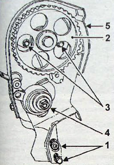
Pic. 1.44. Bolt Location (3) fastening the upper inner casing (5), bolts (1) fastening the inner casing, camshaft pulley (2) and tensioner of the gas distribution mechanism (4)
- Remove the camshaft pulley.
- Remove the two bolts securing the inner timing belt casing.
- Remove the timing tensioner
- Remove the upper inner casing (5) gas distribution mechanism
- Remove the exhaust pipe.
- Remove the exhaust manifold support bracket.
- Remove bolt 1 (Fig 1.45) fastening the coolant pipe Remove the throttle body and fuel distribution line. When removing the fuel rail, be careful not to drop the gaskets.
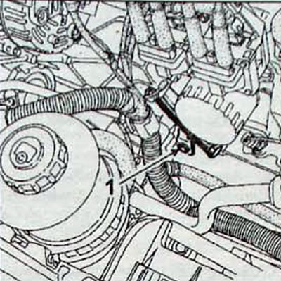
Pic. 1.45. Bolt location (1) coolant pipe fastenings
- Remove the cylinder head bolts and remove it from the engine.
- Remove the cylinder head gasket.
Cleaning and checking
- It is important not to scratch the mating surfaces of aluminum parts. Use Decapjoint to dissolve stuck gasket residue. Apply the product to the surface to be cleaned, wait approximately ten minutes, then remove any remaining gasket with a wooden spatula. This operation must be performed very carefully so that foreign particles do not get into the pressure oil supply channels to the camshaft, which run in the cylinder block and in the cylinder head. Failure to comply with this requirement can lead to clogging of the oil passages and failure of the camshaft.
- Using a ruler and a set of feeler gauges, check for deformation of the mating surface of the cylinder head (pic. 1.46) Regrinding of the cylinder head is not permitted. Maximum deformation: 0.05 mm.
- Measure the height of the cylinder head.
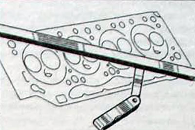
Pic. 1.46. Using a ruler» a set of probes to check the deformation of the mating surface
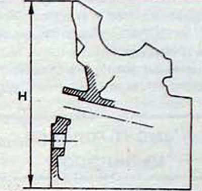
Pic. 1.47. Place (N) Cylinder head height measurements: H=169.5±0.2 mm
Installation
- Before reinstalling the cylinder head, check that the mating surfaces are completely clean. Also check that the holes for the cylinder head bolts in the cylinder block are clean and free of oil
- Check the presence of bushings centering the head on the cylinder block (pic. 1.48).
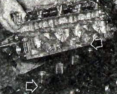
Pic. 1.48. The location of the bushings centering the cylinder head when installing it
- To prevent contact between the pistons and the valves, rotate the crankshaft to such a position that the pistons are in the middle of their stroke.
- Install a new cylinder head gasket.
- Install the cylinder head onto the cylinder block, centering it along the guide bushings.
Note. To secure the cylinder head, new bolts, threads and head bases must be used, which must be lubricated with engine oil.
- Screw in the cylinder head bolts and tighten them in several stages in the sequence shown in Figure 1.49.
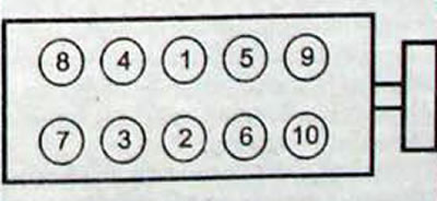
Pic. 1.49. Sequence of tightening the cylinder head bolts of the F3R engine
- 1st stage - torque 30 Nm
- Stage 2 - turn to an angle of 50±4°Wait at least 3 minutes
- Stage 3 - unscrew bolts 1 and 2 by 180°, then first tighten the bolts to a torque of 25 Nm and then tighten to an angle of 123±7°Repeat stage 3 for bolts 3-4, 5-6, 7-3, 9-10. No further tightening of the bolts is required.
Further installation is carried out in the reverse order of removal.