



Attention
- Tensioning the drive belt is an important operation, as the service life of the belt depends on it.
- Using the Tronic 105.6 frequency meter allows you to set the tension level in accordance with the manufacturer's recommendations and avoid over- or under-tensioning and the associated noise and other problems.
- Failure to strictly adhere to the requirements for performing tensioning using the Tronic 105.6 device may result in engine destruction (Fig. 1.25)
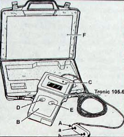
Fig. 1.25. Tronic 105.6 device for adjusting the tension of drive belts A - reading head with two sensors (a) and (b); B - case with indicator; C - reference frequency generator (512±1 Hz), built into the housing; D - device power button; E - button for turning on the instrument calibration control; F - instructions for using the device
- Turn on the power and bring the reading head closer (A, Fig. 1.25) to the branch of the belt whose tension is being checked.
- Position the head at distance X (fig. 1.26,1.27) approximately 5 to 10 mm from the belt.
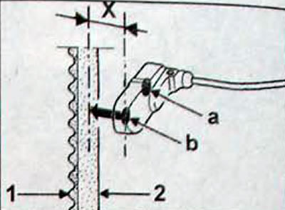
Fig. 1.26. Measuring the tension of the timing belt using the sensor (b) of the reading head: X - distance between the sensor and the belt branch, equal to 5-10 mm; 1 - working side of the belt, 2 - back side of the belt
This note was copied from the resource: www.RENAULTBOOK.ru
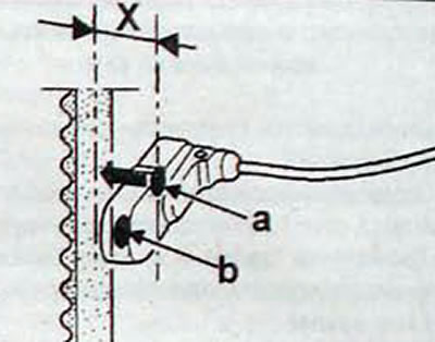
Fig. 1.27. Measuring the tension of the timing belt using the sensor (a) of the reading head; X - distance between the sensor and the belt branch, equal to 5-10 mm
- The measurement can be taken from either side (1) or side (2), depending on the dimensions.
- Any of the sensors "a" or "b" can be used for measurement, provided that the sensor for control must be outside the measurement zone.
- During measurement, do not allow both sensors to be positioned opposite the belt at the same time (fig. 1.28. 1.29).
- The tension measurement is carried out by vibration of the belt, obtained by pulling the belt with a finger and releasing it (Fig. 1.30). The reading is confirmed by an audible signal.
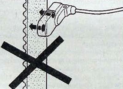
Fig. 1.28. Inadmissible location of both sensors when measuring belt tension
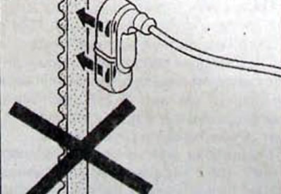
Fig. 1.29. Inadmissible location of both sensors when measuring belt tension
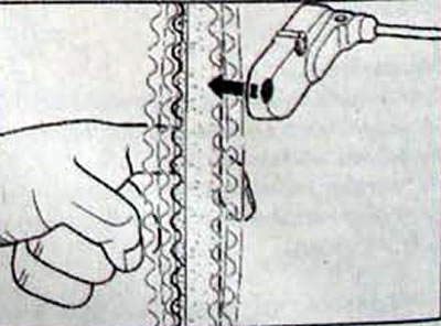
Fig. 1.30. Creating belt vibration when measuring its tension