
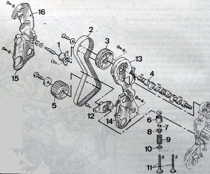
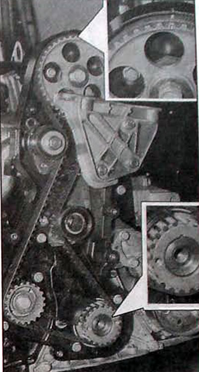
Pic. 1.18. Timing belt/mechanism: 1 - tension roller; 2 - timing belt; 3 - camshaft pulley; 4 - camshaft; 5 - intermediate shaft pulley (F3R 728 engine) or idler pulley (engine /F3R 768); 6 - pusher; 7 - crackers; 8 - upper spring plate; 9 - valve spring; 10 - oil deflector cap; 11 - valves; 12 - tension roller; 13 - internal upper casing; 14 - internal lower casing; 15 - lower timing belt casing; 16 - upper toothed belt casing
Note. To check the tension of the timing belt, you must use the Tronic 105.6 tool.
Removal
Place the car on a two-post lift and lift the front wheels.
Disconnect the cable from the negative terminal of the battery.
Remove:
- right front wheel;
- right lower shield of the engine compartment:
- front right wheel arch protective liner;
- the intake pipe of the exhaust system.
Set the piston of the first cylinder to TDC. Turn the engine crankshaft with a wrench using the central bolt securing the pulley to the crankshaft in the direction of its normal rotation. You can also turn the crankshaft with the front wheel raised and the 4th or 5th gear engaged using the Mot. 1054 fix the piston of the 1st cylinder at TDC.
Pic. 1.19. Installation location and dimensions of the Renault MoL 1054 clamp for fixing the piston of the 1st cylinder at TDC
Use a wooden support to support the engine from below on the right side.
Remove:
- pendulum suspension bracket and travel stop;
- the casing of the timing belt drive.
- crankshaft pulley;
- lower timing belt cover;
- accessory drive belt.
Unscrew the nut and bolt securing the tension roller and loosen the tension on the timing belt.
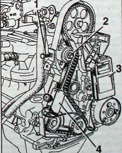
Disconnect the suspension bracket (3, fig. 1.20) from the cylinder head.
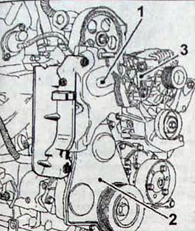
Pic. 1.20. Top location (1) and lower (2) timing belt housings and pendulum suspension bracket (3)
Unscrew the bolts and remove the timing belt covers.
Release the tension roller (T, fig. 1.21) timing belt. If you loosen the idler pulley nut more than one turn, the idler pulley may come off the axle.
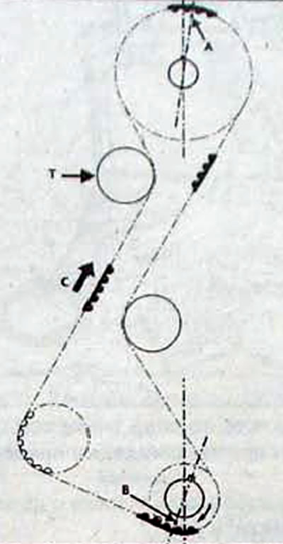
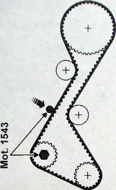
Pic. 1.21. Timing belt: T - tension roller; C - belt installation direction; A and B - points between which there should be 61 vertices of the belt teeth
Remove the timing belt. When removing a timing belt without replacing it, make sure that there are marks on the belt indicating the direction of its rotation. If the marks are worn off, apply marks in front of the marks on the camshaft and crankshaft pulleys.
Note. The timing belt cannot be removed without first removing the pendulum suspension bracket.
Installation
Pic. 1.22. Installing the timing belt
Attention: When replacing the timing belt, it is advisable to replace the tension roller.
- Do not turn the engine crankshaft in the opposite direction to the operating direction.
- Make sure that the TDC lock Mot. 1054 is in place.
- Install the timing belt and pendulum suspension bracket onto the cylinder head, aligning the marks on the belt and pulleys. Pre-tension the timing belt by tightening the M6x45 bolt on the rear timing case.
- Install tool Mot. 1505.
- Tension the timing belt.
- With special tool Mot. 1543-02 with intermediate shaft and Mot. 1543-03 without an intermediate shaft and with a torque wrench set to a tightening torque of 11 Nm, apply preliminary force to the belt branch, the tension of which is adjustable.
- Place the Tronic 105.6 read head and take a measurement, then adjust the tension by rotating the tensioner bolt until the pretension value T1 is reached.
- Tighten the tensioner.
- Rotate the crankshaft four turns and set the timing belt again to the top dead center position.
- Using a special tool and a torque wrench with a tightening torque of 11 Nm, apply preliminary force to the belt branch, the tension of which is adjustable
- Apply the Tronic 105.6 read head and take a measurement, then adjust the tension by rotating the tensioner bolt until the pretension value T2 is reached.
- Remove the tension sensor.
- Installation belt tension, units SEEM 29
- Minimum permissible operating tension, units SEEM 27
Installation belt tension. Hz:
- T1 83±3
- T2 77±5
Pic. 1.23. Timing belt tension: 1 - bolt M6x45; 2 - tension roller fastening nut; 3 - device for checking belt tension Tronic 105.6; 4 - tension check sensor
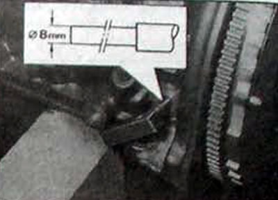
Pic. 1.24. Location of the reference point and the point of application of preliminary force, using a special tool, tighten the bolt lock nut to a torque of 50 Nm.
Note. Be sure to replace the crankshaft pulley mounting bolt with a new one, tighten it to a torque of 20 Nm, then tighten it to an angle of 115±15°.
- Finally install the pendulum suspension bracket.
- Using the centering fork Mot. 1289-02 center the travel stop of the pendulum suspension.
- Carry out further installation in the reverse order of removal.