
Required special tool
Mot. 1273 Belt tension gauge.
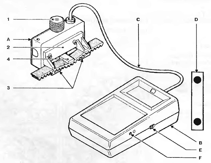
Fig 1.4a:
A - Measuring block;
B - Receiving unit with display;
C - Connecting cable;
D - Plate for control calibration.
Principle of operation
The measuring unit with the help of the handle 1 of the pressure device regulator 2 and the outer tabs 3 gives the belt a constant deflection. The reaction force of the belt is measured using the control plate 4, equipped with strain gauges. Stretching strain gauges leads to a change in their resistance. This change, converted by the instrument, is shown on the display in SEEM units (US).
Instrument calibration
The device has been adjusted by the manufacturer, but every six months it is necessary to carry out a control check of its readings.
Measurement method
Zero setting:
- turn on the instrument power (button E) when handle 1 is at the bottom of the measuring block;
- if the display shows 0, then the device can be considered ready for operation;
- if there is no indication on the display, check the condition of the battery of the device with a nominal voltage of 9 V;
- if the display shows a value other than 0, setting to 0 is done by turning the screw F.
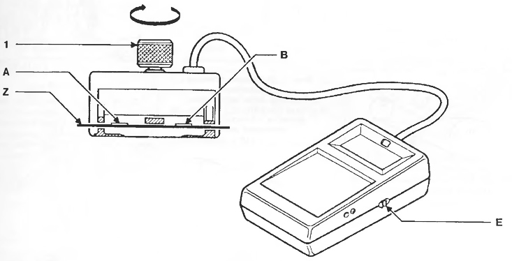
Pic. 1.4b
Checking the calibration
Power on the instrument (button E).
Place the Z reference plate into the measuring block as shown in the figure (engraved control marks up, A - minimum value, B - maximum value). Turn the knob 1 of the pressure device regulator to the third click, thereby preparing the device for operation.
Make sure the display shows an X value between A and B (A < X
Table 1.4
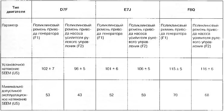
D7F engine
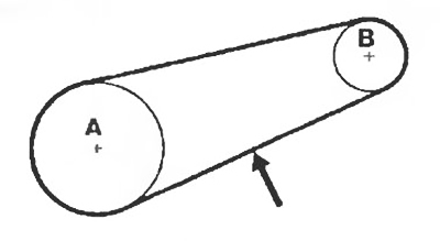
Pic. 1.5a. Alternator drive belt:
A - Crankshaft pulley;
B - Generator pulley;
-> - Belt tension control point.
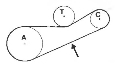
Pic. 1.5b. Power steering pump drive belt:
A - Crankshaft pulley;
C - Power steering pump pulley;
-> - Belt tension control point.
E7J engine
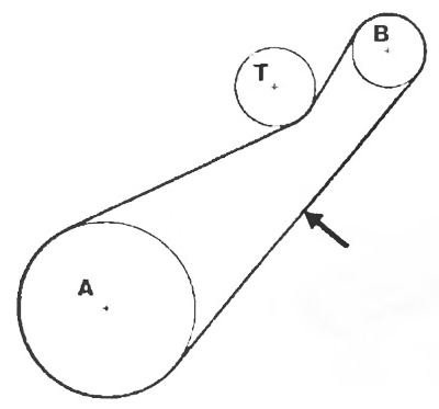
Pic. 1.6a. Alternator drive belt:
A - Crankshaft;
B - Generator;
T - Tension roller;
-> - Belt tension control point.
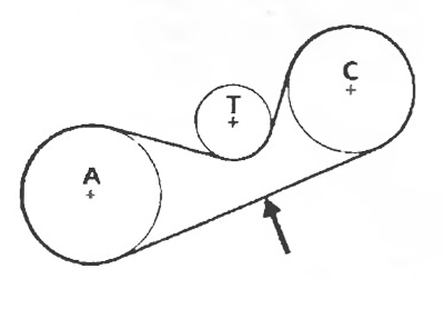
Pic. 1.6b. Power steering pump drive belt:
A - Generator pulley;
C - Power steering pump pulley;
T - Tension roller;
-> - Belt tension control point.
F8Q engine
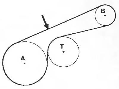
Pic. 1.7a. Alternator drive belt:
A - Crankshaft pulley;
B - Generator pulley;
T - Tension roller;
-> - Belt tension control point.
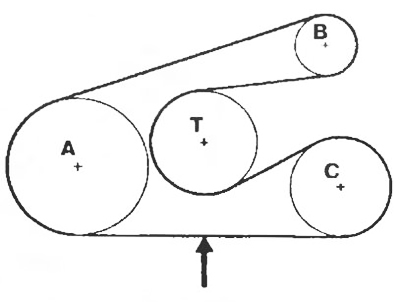
Pic. 1.7b. Power steering belt F8Q:
A - Crankshaft pulley;
B - Generator pulley;
C - Power steering pump pulley;
T - Tension roller;
-> - Belt tension control point.