
Power supply
The engine control unit is powered by a constant voltage of 12 V through pin 32 of the connector. The power circuit through pin 32 supports power supply to the control unit memory and is protected by fuse F10 3A, located in the vehicle interior.
When the ignition is turned on, battery voltage is supplied to pin 24 of the engine control unit connector through fuse F38 30 A located in the vehicle interior. In response to this, the engine control unit connects pin 48 of the connector to «mass», which leads to the short circuit of the fuel pump power supply. The fuel pump power relay supplies voltage to pin 52 of the engine control unit connector and powers the fuel pump, activated charcoal canister solenoid valve, idle speed control, cylinder recognition sensor at the beginning of the intake stroke, Lambda sensor and injectors. Simultaneously, if no attempt is made to start the engine after 1 second (there is no signal from the engine crankshaft position sensor), the engine control unit breaks the electrical circuit connecting pin 48 of the connector to «mass», thus cutting off power to some elements of the fuel system. This power will only be restored if the engine control unit receives a signal from the crankshaft speed sensor.
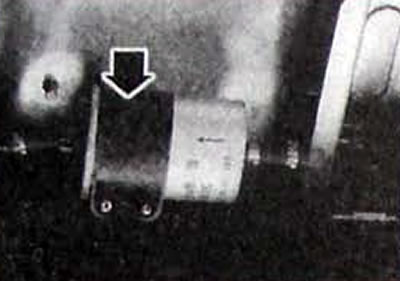
Inertial sensor (switch) shock is designed to disable the electrically driven fuel pump. if the car has been subjected to a significant impact, which eliminates the risk of the car catching fire. If after the collision the car engine does not start, the impact sensor may have been activated, therefore, pressing the button protected by the elastic casing must turn on the switch.
Fuel system operation
Pic. 1.5. Installing the fuel filter, the arrow on the filter must coincide with the direction of fuel flow or mark «OUT» should be directed towards the right side of the car
An electric fuel pump located in the fuel tank supplies fuel under pressure to the fuel line through the fuel filter. The pressure regulator maintains pressure at 2.5-3 bar regardless of the fuel consumption of the fuel injectors, returning excess fuel to the fuel tank.
The fuel vapor recovery system prevents fuel vapor from evaporating into the atmosphere from the fuel tank, thereby preventing the formation of photochemical smog. The fuel tank plug is completely sealed, and there is a tube connected to a canister of activated carbon to remove fuel vapors
Fuel vapor is accumulated in a canister with activated carbon. When the engine is running, the electronic control unit opens the valve, and fuel vapor enters the engine, where it is burned.
Air supply system
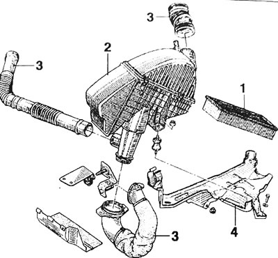
Pic. 1.6. Air supply system: 1 - air filter; 2 - air filter housing; 3 - air pipes; 4 - bracket
Fresh air is taken in at the upper left side of the engine compartment and cleaned by a filter. One solenoid valve, which acts as an idle speed control, allows a certain small amount of air to bypass the throttle valve and controls the idle speed of the crankshaft depending on the operating conditions of the engine.
Ignition system
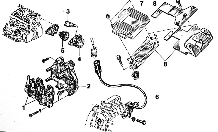
Pic. 1.7. Ignition system elements:1 - ignition coils; 2 - ignition coil mounting bracket; 3 - cylinder recognition sensor at the beginning of the intake stroke; 4 - cap; 5 - cylinder detection sensor; 6 - TDC mode/position sensor; 7 - control unit for the fuel injection and ignition system; 8 - bracket
The ignition system is designed to ignite the air-fuel mixture in each cylinder at a precisely set point in time. In gasoline engines this is achieved by an electric spark (electrical discharge), created between the spark plug electrodes.
The static ignition system differs from the classical ignition system in the absence of an ignition distributor and the presence of two ignition coils with two power contacts.
The system consists of:
- an injection system control unit with an ignition power module integrated into it;
- two ignition coils with double power contact;
- four spark plugs;
- noise suppression capacitor.
The injection system control unit, depending on the signals from the crankshaft position sensor, pressure sensor and other sensors, but mainly based on data on the load and engine speed, determines the optimal ignition timing in accordance with the program.
The ignition signal is transmitted by the control unit to the switch, which controls two ignition coils. Sparking occurs simultaneously on two spark plugs of those cylinders whose pistons are in the TDC area, by breaking the chain «masses» corresponding ignition coils. The two ignition coils each have two power contacts and are controlled separately by the injection system control unit.
The ignition coils are equipped with three-pin electrical connectors in different colors.
One ignition coil has a black electrical connector and generates simultaneous high-voltage pulses for the spark plugs of the 1st and 4th cylinders and is controlled via channel 28 of the injection unit.
The second ignition coil has a gray electrical connector and generates simultaneous high-voltage pulses for the spark plugs of the 2nd and 3rd cylinders and is controlled via channel 29 of the injection unit.
Both ignition coils are connected to one noise suppression capacitor.
The flywheel ring gear consists of 60 identical teeth of a certain size, located at an equal specified interval. Two teeth are missing, thereby forming an absolute position mark located at an azimuth of 84° (or 14 teeth around the circumference) to the TDC position of the pistons of the 1st and 4th cylinders. That is, in fact the crown has 58 teeth.
Principle of operation
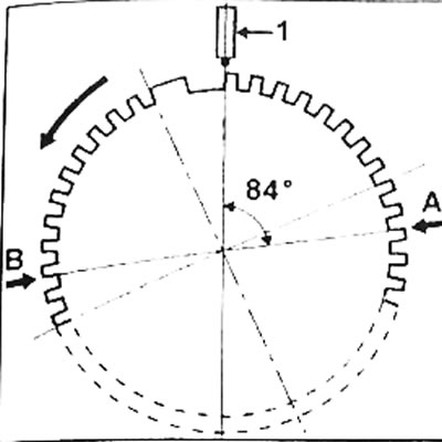
Pic. 1.8. The location of the teeth on the flywheel: A - TDC position of the pistons of the 1st and 4th cylinders; B - TDC position of the pistons of the 2nd and 3rd cylinders; 1 - mode sensor
Cylinders 1 and 4 are at top dead center when the location indicated by the arrow (A, fig. 1.8). passes in front of the mode 1 sensor.
Cylinders 2 and 3 are at top dead center when the location marked by arrow B passes in front of the mode sensor (1, fig. 1.8).
The injection system control unit recognizes the TDC position of the pistons of cylinders 1 and 4 by the passage of the 15th tooth in front of the crankshaft sensor (after elongated tooth). As a result, the injection control unit, by counting the number of teeth, determines the angle before TDC of the pistons when ignition should be carried out, depending on the currently required calculated ignition timing. TDC of the pistons of the 2nd and 3rd cylinders is determined by the passage of the 45th tooth in front of the crankshaft sensor (after elongated tooth).
Note. Correction of the ignition timing is also carried out based on the signal from the knock sensor.
Removing the cylinder detection sensor
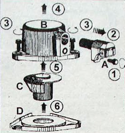
Pic. 1.9. The sequence for removing the cylinder detection sensor is: A - cylinder detection sensor; B - cap; C - target; D - protection plate
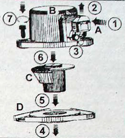
Pic. 1.10. Sequence for installing the cylinder detection sensor: A - cylinder detection sensor B - cap; C - target; D - protection plate
- Disconnect the electrical connector from the sensor.
- Unscrew one bolt and remove the cylinder detection sensor (A. fig. 1.9).
- Unscrew the three bolts and remove the cap (IN).
- Target (WITH) is held at the end of the camshaft by a retaining ring. To remove the target, place the end of the drift on the back of the target, apply short gentle blows to the drift with a hammer and remove the target (WITH) and a plastic protective plate (D).
Attention. Be sure to follow the following installation sequence for the cylinder detection sensor, as otherwise this may result in sensor malfunction and/or failure.
Installing the cylinder detection sensor
- Install the sensor on the cap, press it up and tighten to a torque of 15 Nm
- Install the plastic protective plate.
- Install a target that has an element on it that prevents it from being installed incorrectly. Before inserting the target into the camshaft, check that it is positioned correctly.
- Install the cap with the sensor and tighten the three bolts securing the cap to a torque of 10 Nm.
Adjusting the camshaft position sensor clearance
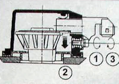
Pic. 1.11. Camshaft position sensor clearance adjustment sequence
- The adjustment consists of releasing the sensor mounting bolt without touching the sensor and tightening the bolt to a torque of 8 Nm.
- When the bolt is released, the sensor is released and a spring built into the cover pushes the sensor towards the target.
- When the bolt is tightened, the sensor is fixed.
- The sensor has two plastic grooves that contact the target. These grooves are partially erased during the very first revolutions of the target after starting the engine, as a result of which there is no direct contact and the gap is adjusted.
If the grooves are completely worn out, the gap cannot be adjusted and the sensor must be replaced.
Attention. After installing the sensor, you need to check its adjustment. To do this, use the voltmeter function of the XR25 diagnostic tool. On the connected sensor, slide the rubber protective cap of the connector. Start the engine and check the voltage at pin No. 2 of the sensor (contact in the center). The voltage displayed by the device should alternate (then 0, then 12 V). Otherwise, readjust the sensor.
Anti-theft engine immobilizer
The car is equipped with a 2nd generation anti-theft engine blocking system.
Replacing the fuel injection system control unit
Fuel injection control units are supplied as spare parts uncoded but ready for coding.
When replacing a unit, you need to enter a code unique to each car. then check the operation of the engine immobilizer system. To do this, just turn on the ignition for a few seconds, then turn it off and remove the key from the ignition.
Checking the operation of the engine immobilizer system
Remove the key from the ignition, and after 10 seconds the red engine immobilizer warning light should flash.
Operation of the injection system and air conditioning system When the air conditioning system is turned on. The crankshaft frequency at idle speed increases to 900 min-1. Under certain operating conditions, the injection system control unit prohibits the inclusion and operation of the compressor.
Turning on the compressor is prohibited for 10 seconds after starting the engine. The compressor will not turn on if the coolant temperature is more than 115°C. The inclusion and operation of the compressor is prevented if the engine crankshaft speed exceeds 6000 min-1.