



This section only briefly describes the injection system malfunctions caused by failure of certain sensors. The procedure for removing and installing units of the fuel and engine control systems is given in the subsections "Power supply system" and "Engine Management System".
The feedback injection system includes a catalytic converter of exhaust gases and an oxygen concentration sensor in the exhaust gases, which provides feedback. The sensor monitors the oxygen concentration in the exhaust gases, and the electronic control unit, using its signals, maintains such an air-fuel ratio at which the converter operates most effectively. Renault Logan cars can also be equipped with a second oxygen concentration sensor at the outlet of the converter. Moreover, the main control sensor is the sensor installed on the exhaust manifold, and the sensor installed at the outlet of the converter is a diagnostic one and determines the quality of operation of the entire engine management system as a whole. If the engine control unit, using information from the diagnostic sensor, detects an excess of oxygen concentration in the exhaust gases, which cannot be corrected by calibrating the system using signals from the control sensor and which indicates some kind of system malfunction, it will turn on the engine malfunction indicator lamp in the instrument cluster and enter the error code into memory for subsequent diagnostics.
Caution: Before removing any fuel injection system components, disconnect the negative battery cable.
Disconnect the battery only when the ignition is off.
Do not start the engine if the battery cable terminals are not tightly tightened.
Never disconnect the battery from the vehicle's electrical system while the engine is running.
When charging, disconnect the battery from the vehicle's electrical system, as increased current during charging may damage electronic components.
Do not allow the electronic control unit (ECU) to heat up above 65°C when operating and above 80°C when not operating (for example, in a drying chamber). It is necessary to remove the ECU from the car if this temperature is exceeded.
Do not disconnect or connect the wiring harness connectors to the ECU with the ignition on.
Before performing arc welding on a vehicle, disconnect the wires from the battery and the wire connectors from the ECU.
All voltage measurements should be performed using a digital voltmeter with an internal resistance of at least 10 MΩ.
The electronic components used in the injection system are designed for very low voltage, so they can easily be damaged by electrostatic discharge. To prevent damage to the ECU by electrostatic discharge:
- - do not touch the ECU connectors or electronic components on its boards with your hands;
- - when working with the programmable read-only memory (PROM) of the control unit, do not touch the microcircuit terminals.
It is not allowed to operate an engine with a neutralizer on leaded gasoline - this will lead to rapid failure of the neutralizer and oxygen concentration sensors.
When working in rainy weather, do not allow water to come into contact with the electronic components of the fuel injection system.
Check the injection system in the following order.
1. Check the ground connection of the engine and battery.
2. Check the electric fuel pump and fuel filter.
3. Check the fuses and relays for switching on the injection system elements.
4. Check the reliability of the contacts in the pads with wires of the injection system elements.
5. Check the injection system sensors.
The vast majority of fuel injection system faults are caused by failure of the following sensors:
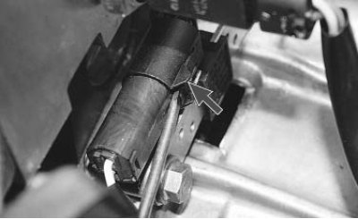
- top Dead Center (TDC) and Crankshaft Speed Sensor (mounted on the clutch housing) - complete failure of the injection system, the engine does not start;
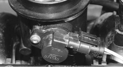
- throttle position sensor (mounted on the throttle body) - loss of power, jerks and dips during acceleration, unstable operation in idle mode;
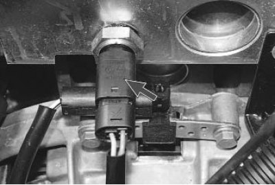
- coolant temperature sensor - difficulty starting in cold weather: you have to warm up the engine, maintaining the speed with the accelerator pedal, when overheating, the power is significantly reduced, detonation appears;
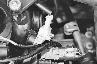
- intake air temperature sensor - if the sensor fails, fuel consumption increases, and the level of toxicity of exhaust gases increases;
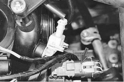
- absolute pressure sensor (rarefaction) in the intake pipe - if the sensor fails, fuel consumption increases, dynamics significantly deteriorates, problems with starting the engine;
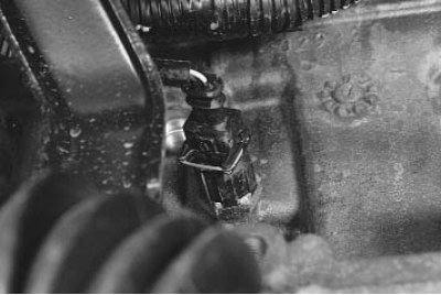
- knock sensor (installed on the right side of the cylinder block in the area of the 2nd and 3rd cylinders) - the engine is very sensitive to the quality of gasoline, increased tendency to detonation;
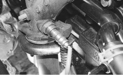
- exhaust gas oxygen concentration sensor (lambda probe) mounted on the exhaust manifold (for clarity, the collector heat shield has been removed) - increased fuel consumption, decreased engine power, unstable idling. Possible damage to the catalytic converter of exhaust gases;
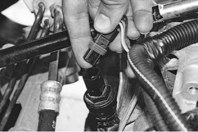
- speed sensor (mounted on the gearbox housing) - the vehicle's dynamic performance may deteriorate and fuel consumption may increase. Check the reliability of the connection of the wiring harness to the sensor block and clean its contacts from oxides.