
The control device in the system is an electronic control unit (ECU). Based on the information received from the sensors, the ECU calculates the parameters for fuel injection control and ignition timing control. In addition, in accordance with the embedded algorithm, the ECU controls the operation of the electric motor of the fan of the engine cooling system, the electromagnetic clutch for turning on the air conditioning compressor, performs the function of self-diagnostics of the system elements and notifies the driver of any malfunctions.
The engine management system, along with the electronic control unit, includes sensors, actuators, connectors and fuses.
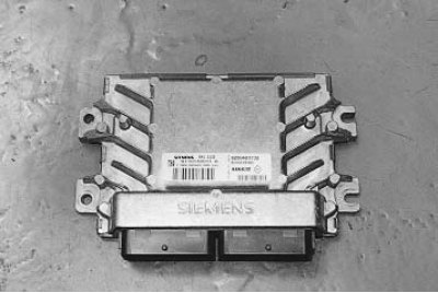
Electronic control unit (ECU) connected by electrical wires to all sensors of the system. Receiving information from them, the block performs calculations in accordance with the parameters and control algorithm stored in the memory of a programmable read-only memory device (ROM), and controls the executive devices of the system. The program variant recorded in the ROM memory is indicated by the number assigned to this ECU modification.
The control unit detects a malfunction, identifies and stores its code, even if the failure is unstable and disappears.
After repair, the fault code stored in the memory of the control unit must be erased.
The unit supplies 5 and 12 V direct current to various sensors and switches of the control system. Since the electrical resistance of the power circuits is high, the test lamp connected to the system outputs does not light up. To determine the supply voltage at the computer terminals, a high impedance voltmeter should be used (10 MΩ). The control unit is located in the engine compartment behind the battery under a common cover with relays and fuses and is connected to the wiring harness with one 40-pin connector. The ECU is not serviceable and should be replaced if it fails.
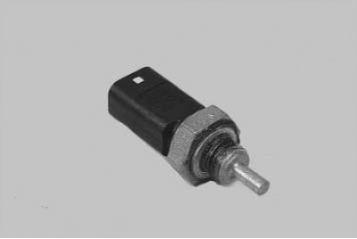
The coolant temperature sensor is installed in the engine cooling system. The sensing element of the sensor is a thermistor, its electrical resistance changes inversely with temperature.
The electronic unit feeds the sensor circuit with a constant reference voltage. The sensor signal voltage is maximum on a cold engine and decreases as it warms up. Based on the voltage value, the electronic unit determines the engine temperature and takes it into account when calculating the injection and ignition control parameters.
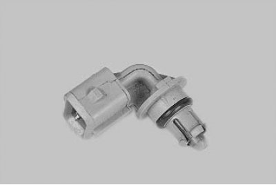
The intake air temperature sensor is similar in design to the coolant temperature sensor, it also uses a thermistor that changes its resistance depending on temperature.
The ECU supplies the sensor circuit with a constant reference voltage. The signal voltage of the sensor is maximum when the air in the intake pipe is cold and decreases as its temperature rises. From the voltage value, the ECU determines the intake air temperature and makes adjustments when calculating the ignition timing.
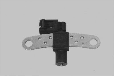
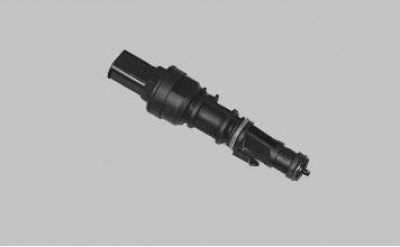
The sensor of the top dead center and the speed of the crankshaft of the inductive type is designed to synchronize the operation of the electronic control unit with the TDC of the piston of the 1st cylinder and the angular position of the crankshaft.
The sensor is installed at the rear of the engine opposite the driving ring on the engine flywheel. The crown is a toothed wheel with cavities. Two teeth sheared to create a sync pulse («reference» momentum), which is necessary to coordinate the operation of the control unit with the TDC of the pistons in the 1st and 4th cylinders.
As the crankshaft rotates, the teeth change the sensor's magnetic field, inducing AC voltage pulses. The control unit determines the crankshaft speed from the sensor signals and sends pulses to the injectors.
If the sensor fails, the engine cannot be started.
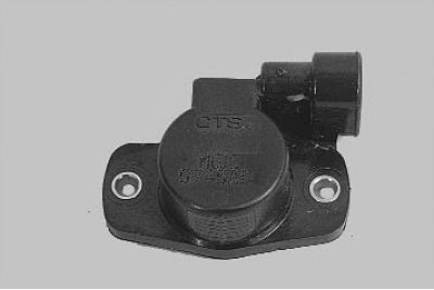
The throttle position sensor is mounted on the side of the throttle assembly and is connected to the throttle valve axis.
The sensor is a potentiometer, one end of which is supplied with «plus» supply voltage, the other end is connected to «weight».
From the third output of the potentiometer (from the slider) is the output signal to the electronic control unit.
When the throttle is turned (from impact on the control pedal), the voltage at the output of the sensor changes. When the throttle is closed, it is minimal. When the damper opens, the voltage at the output of the sensor rises and reaches its maximum value when the damper is fully open.
By monitoring the output voltage of the sensor, the controller adjusts the fuel supply depending on the throttle opening angle (those. at the request of the driver).
The throttle position sensor does not require adjustment, as the control unit perceives idling (those. full throttle closing) as a zero point.
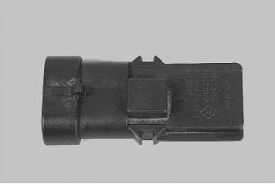
Absolute pressure sensor (rarefaction) in the intake pipe converts the pressure in this pipe into an electrical voltage, by the value of which the electronic control unit determines the engine load. The sensor is installed on the intake pipe. When the engine is not running, the control unit determines the atmospheric pressure from the sensor voltage and adapts the injection control parameters to the specific height above sea level. The atmospheric pressure values stored in the memory are updated periodically when the vehicle is in steady motion and during full throttle opening.
The vehicle speed sensor is installed on the gearbox. The principle of operation of the sensor is based on the Hall effect. The sensor outputs rectangular voltage pulses to the electronic control unit with a frequency proportional to the speed of rotation of the drive wheels.
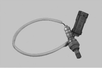
Oxygen concentration sensor (Lambda probe) screwed into the threaded hole in the exhaust manifold. A galvanic cell is located in the metal bulb of the sensor, washed by the flow of exhaust gases. Depending on the oxygen content in the exhaust gases, as a result of the combustion of the air-fuel mixture, the voltage of the sensor signal changes.
Information from the sensor enters the electronic control unit in the form of low and high level signals. With a low level signal, the control unit receives information about the high oxygen content and, therefore, about the lean mixture. A high level signal indicates a low oxygen content in the exhaust gases and, therefore, a re-enrichment of the mixture.
Constantly monitoring the voltage of the sensor signal, the control unit adjusts the amount of fuel injected by the injectors. When the sensor signal is low (lean air-fuel mixture) the amount of fuel supplied increases, with a high signal level (rich mixture) - decreases.
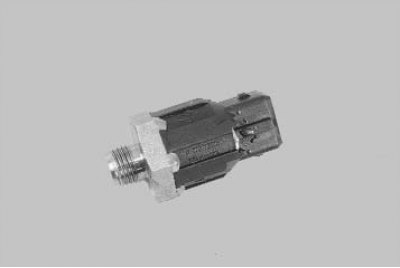
A knock sensor attached to the cylinder block between cylinders 2 and 3 detects abnormal vibrations (detonation strikes) in the engine.
The sensitive element of the sensor is a piezoelectric plate. When detonation occurs, voltage pulses are generated at the output of the sensor, which increase with increasing intensity of detonation impacts. The ECU corrects the ignition timing based on the signal from the sensor to eliminate detonation flashes of fuel.
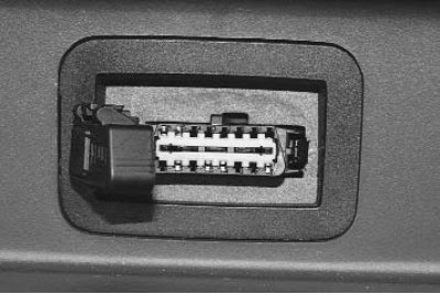
The diagnostic connector is used to display fault codes from the ECU memory detected during the operation of the engine management system.
The diagnostic connector is located in the glove box on its rear wall. A scanning device can be connected to the diagnostic connector, which reads error information from the computer memory.
Wiring diagrams for the engine management system are given at the end of the book.