



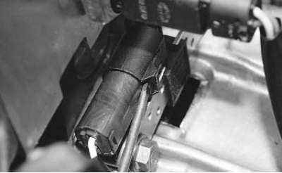
The top dead center and crankshaft speed sensor, consisting of a magnet and a winding, is mounted on top of the clutch housing.
If a fault occurs in the sensor circuit, the engine stops running, the controller stores a fault code in memory and turns on the warning light in the instrument cluster. In this case, check the sensor and the ring gear for missing teeth, runout or other damage.
You will need: a 10 mm wrench, a tester.
1. Disconnect the wire from the negative terminal of the battery.
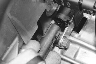
2. Disconnect the sensor wiring harness connector.
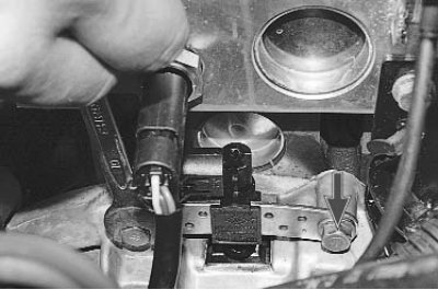
3. Remove the two sensor mounting bolts...
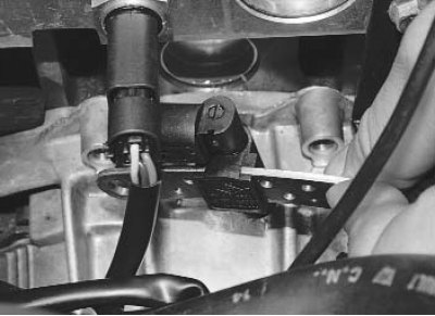
4. ...and remove the sensor.
5. Install the TDC/Crankshaft Speed Sensor in the reverse order of removal.
Note: To ensure that the fuel injection system is working properly after replacing the top dead center and crankshaft or flywheel speed sensor, it is necessary to perform a check using a special device, which includes the following:
- deceleration of the vehicle with the fuel supply cut off in 2nd, 3rd, 4th or 5th gear at an engine speed of 3500–3000 min⁻¹ for at least 2 s;
- repeated deceleration with fuel cut-off in 2nd, 3rd, 4th or 5th gear at an engine speed of 2400–2000 min⁻¹ for at least 3 s;
- checking for fault codes and troubleshooting if necessary;
- erasing codes.
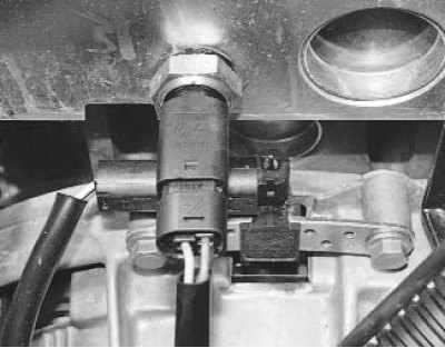
The coolant temperature sensor is installed at the end of the cylinder head on the side of the 1st cylinder.
The sensor is a thermistor with a negative temperature coefficient: the electrical resistance of the sensor decreases with increasing temperature. The ECU processes the sensor signal and sets the optimal enrichment of the working mixture when the engine warms up.
You will need: a 21 mm wrench, a flat-blade screwdriver, a tester, and a thermometer.
1. Disconnect the wire from the negative terminal of the battery.
2. Drain the coolant (see "Replacing the coolant").
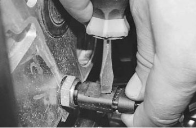
3. Press the lock with a screwdriver...
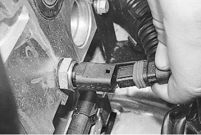
4. ...and disconnect the wiring harness connector from the coolant temperature sensor.
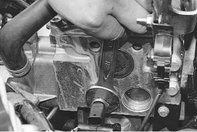
5. Loosen the sensor with a wrench and unscrew it by hand.
6. Install the parts in the reverse order of removal.
7. Fill with coolant.
The throttle position sensor is a potentiometer that is mounted on the throttle axis. Rotation of the throttle axis causes a change in the sensor signal voltage, which the ECU uses to determine the degree of throttle opening.
If the engine does not operate properly at idle or acceleration dynamics deteriorate, check the sensor and its connector.
You will need: TORX T20 key, tester.
1. Disconnect the wire from the negative terminal of the battery.
2. Remove the air filter (see "Removing and installing the air filter").
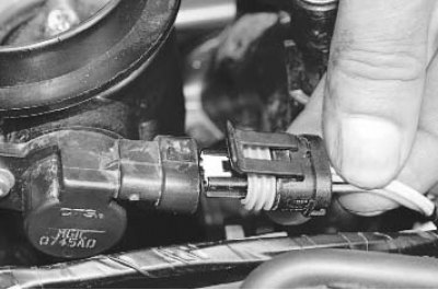
3. Press the lock and disconnect the wiring harness connector from the sensor.
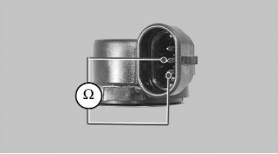
4. Connect the tester in resistance measurement mode to terminals "B" and "C" of the sensor.
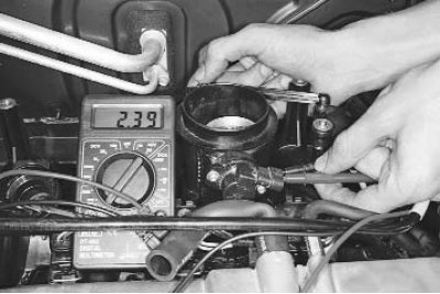
5. Measure the resistance at the sensor terminals with the throttle valve fully closed. It should be 2.3–2.4 kOhm.
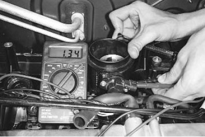
6. Turn the throttle valve by hand until it is fully open and measure the resistance again. It should be 1.3–1.4 kOhm.
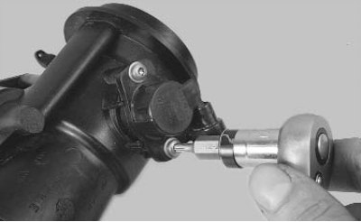
7. To replace the sensor, unscrew the two bolts that secure it (for clarity, shown on a removed throttle assembly)...
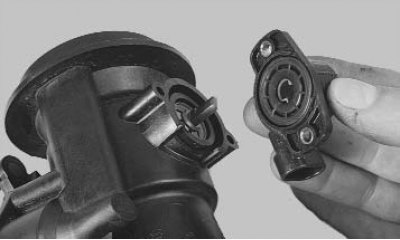
8. ...and remove the throttle position sensor.
9. Install the parts in the reverse order of removal.
Absolute pressure sensor (rarefaction) in the intake pipe is installed on the intake pipe. The sensor records the change in pressure (rarefaction) in the intake pipe depending on the change in load and engine crankshaft speed and converts them into an output signal voltage. Depending on the sensor signal, the ECU calculates the amount of air entering the engine.
1. Disconnect the wire from the negative terminal of the battery.
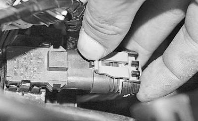
2. Press the latch...
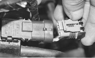
3. ...and disconnect the wiring harness connector from the sensor.
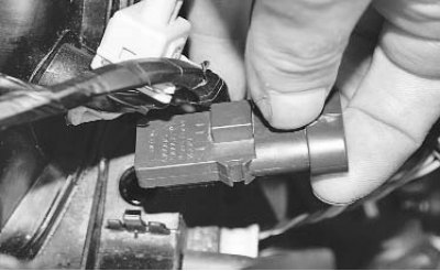
4. Carefully remove the absolute pressure sensor, overcoming the resistance of the sealing rubber rings (the sensor nipple is installed with tension in the hole of the intake pipe).
5. Install the sensor in the reverse order of removal.
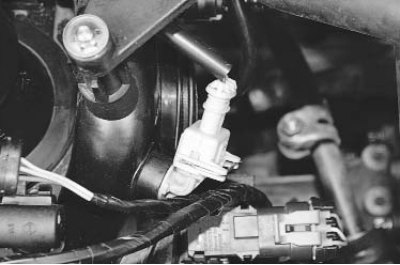
The intake manifold air temperature sensor is installed on the intake manifold near the throttle assembly. The sensor is a thermistor with a negative temperature coefficient: the electrical resistance of the sensor decreases with increasing temperature. Based on the air temperature information from the sensor, the electronic control unit regulates the amount of fuel injected.
You will need a flat-blade screwdriver.
1. Disconnect the wire from the negative terminal of the battery.
2. Remove the air filter (see "Removing and installing the air filter").
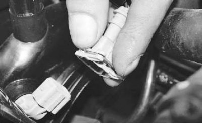
3. Disconnect the wiring harness connector from the sensor by squeezing the spring clip with your fingers.
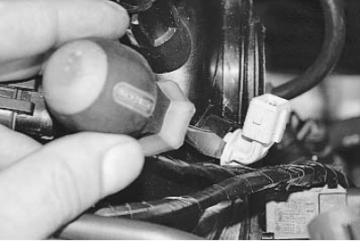
4. Use a screwdriver to pry...
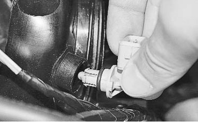
5. ...and remove the sensor.
6. Install the sensor in the reverse order of removal.
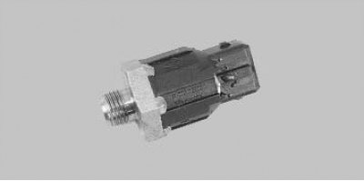
The knock sensor, attached to the cylinder block between cylinders 2 and 3, detects abnormal vibrations (detonation strikes) in the engine.
It is more convenient to replace the sensor on a vehicle installed on a lift, since access to the sensor from above is very difficult.
You will need a 24 key.
1. Disconnect the wire from the negative terminal of the battery.
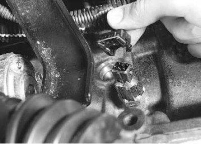
2. Squeeze the retainer and disconnect the wiring harness connector from the sensor.
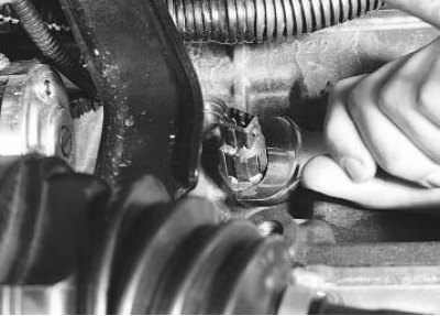
3. Remove the knock sensor...
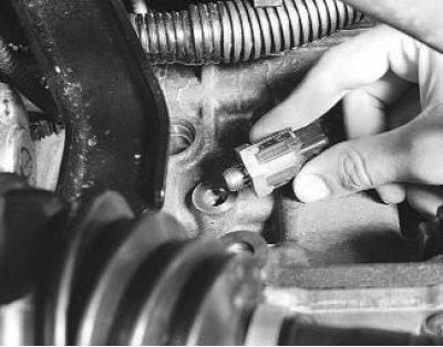
4. ...and remove it.
5. Install the parts in the reverse order of removal.
Oxygen concentration sensor (lambda probe) is installed on the exhaust manifold. On some vehicles, a second sensor is installed behind the catalytic converter. The sensor measures the oxygen content in the exhaust gases and converts the measured value into a signal voltage that is fed to the electronic engine control unit. Using the sensor signals, the ECU controls the fuel injection in such a way as to obtain the calculated composition of the fuel-air mixture.
If the oxygen sensor is faulty, exhaust emissions may increase dramatically.
You will need: keys "10", "22".
1. Disconnect the wire from the negative terminal of the battery.
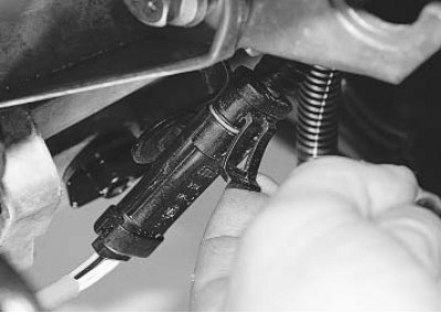
2. Press the latch...
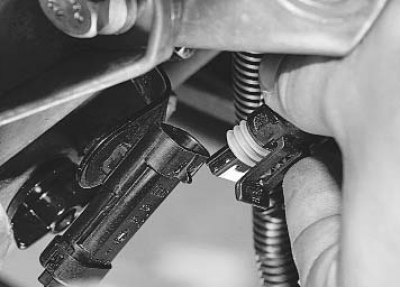
3. ...and disconnect the wiring harness connector.
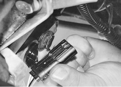
4. Remove the shoe from the bracket by sliding it forward.
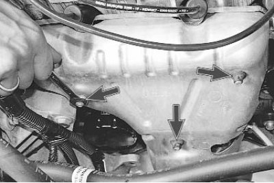
5. Unscrew the three nuts...
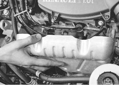
6. ...and remove the heat shield.
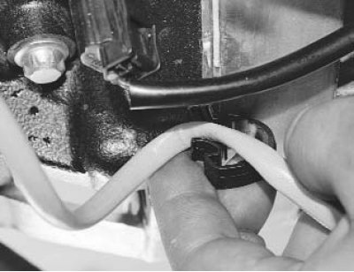
7. Remove the wire from the holder.
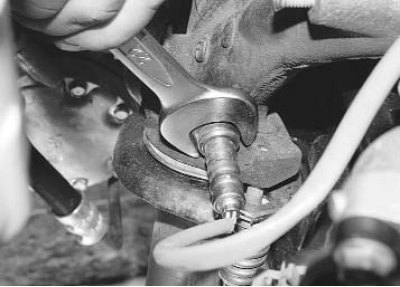
8. Loosen the tightening...
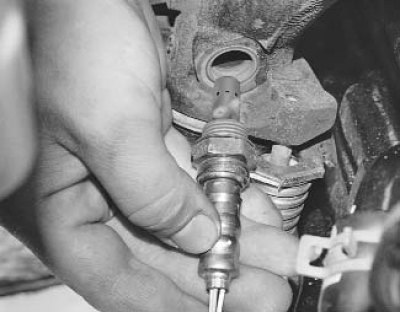
9. ...and unscrew the sensor from the exhaust manifold.
10. Install the sensor in the reverse order of removal.
The vehicle speed sensor is mounted on the gearbox and is a Hall sensor. It sends a pulse signal proportional to the rotation speed of the drive wheels to the electronic engine control unit.
1. To replace the speed sensor, disconnect the wire from the negative terminal of the battery.
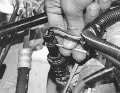
2. Press the latch...
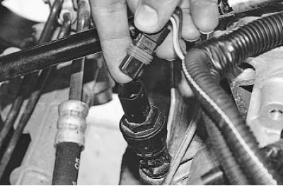
3. ...and disconnect the wiring harness connector from the speed sensor.
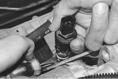
4. Carefully pry up the sensor with a screwdriver...
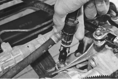
5. ...and remove it from the gearbox housing.
6. Install the speed sensor in the reverse order of removal.