



Contents: Description of the system 🠛 Throttle body with servo drive 🠛 Turning on the signal lights 🠛 ECU contact assignment 🠛 Replacement of system elements 🠛 Configurations and programming 🠛
Description of the system
The system includes:
- ECU Bosch ME 7.4.6;
- throttle body with servo drive (EGAS: Electronic Engine Air Filling System);
- adsorber;
- evaporative Canister Purge Solenoid Valve;
- absolute pressure sensor;
- two fuel distribution rails with three injectors on each of them;
- two camshaft phase regulators;
- 6 finger-type ignition coils and spark plugs;
- 2 camshaft position sensors;
- 2 upstream oxygen sensors;
- 2 downstream oxygen sensors;
- two catalytic converters, one for each bank of cylinders;
- 2 knock sensors;
- coolant temperature sensor;
- oil level and temperature sensors;
- air temperature sensor;
- accelerator pedal module;
- submersible fuel pump assembly with fuel level sensor;
- engine crankshaft position and speed sensor;
- power steering pressure sensor;
- diagnostic connector.
Rows A and 1 of elements correspond to 3 cylinders of the engine located on the side of the electric fans, rows B and 2 of elements correspond to 3 cylinders of the engine located on the side of the vehicle interior.
Cylinders No.1-2-3 are located on the side of the electric fans of the engine cooling system, while cylinder No.1 is located on the flywheel side; cylinders No.4-5-6 are located on the passenger compartment side, while cylinder No.4 is located on the flywheel side.
Note. The injection system ECU is selected for the given engine model and the vehicle on which it is installed. Therefore, checking the ECU on another vehicle and installing it on the previous vehicle is not allowed.
Throttle body with servo drive
General information
Since the throttle valve unit with a servo drive does not provide for the coordination of the actual value obtained on the basis of signals from the sensor conductive tracks and the mechanical position of the throttle valve, it is necessary to adjust 8 ECU ME7.4.6. During adjustment, the throttle valve opening and its reserve position are programmed and the potentiometer amplifier is balanced. The programmed values are entered into the ECU memory. The stages of programming the extreme positions and storing the programmed values constitute the initialization of the throttle valve unit with a servo drive. In addition, the throttle valve springs are checked.
It is essential to perform "initial initialization" when you first turn on the ignition of the vehicle; otherwise the throttle valve may remain in the reserve position. Initialization occurs automatically in autonomous mode with the ignition on and only if certain initial conditions are met; several initialization cycles are possible with one ignition on.
Throttle valve programming procedure
Programming must be performed correctly at least once during the life of the vehicle, when the ignition is first turned on (initial initialization) and every time the ECU or throttle body with servo drive is replaced.
1. Switch on the ignition and wait at least 5 seconds without starting the engine: this will automatically adapt to the throttle position.
2. Turn off the ignition.
3. Wait a while before turning the ignition on again so that the ECU can remember the programmed values:
- at least 10 s with a cold engine (coolant temperature below 85°C);
- not less than 130 s with a hot engine (coolant temperature is greater than or equal to 90°C).
4. Turn on the ignition, start the engine and let it idle for 1 min to properly adapt to the air flow through the throttle body with servo drive.
Note: A fault occurs and a command is issued to set the throttle valve to the reserve position:
- in case of cancellation of the automatic programming procedure (stage 1 above) in less than 5 s and if step 4 is not completed;
- in case of failure to complete step 4.
Programming must be done at re-initialization and each time the ECU or the motorized throttle body is replaced. Turn on the ignition, start the engine and let it idle for 1 min to allow correct adaptation to the air flow through the motorized throttle body.
Programming the throttle valve backup position with servo drive
The reserve position is necessary for adjusting the throttle valve position and determining the need for correction when replacing the throttle valve unit with a servo drive. When the ignition is on, before applying power to the throttle valve drive motor, the reserve valve position signal comes from both conductive tracks of the sensor and its reliability is calculated by comparing with the values stored in the ECU memory. If the values diverge, the need for adjustment and programming of the reserve position is determined.
Checking the throttle springs with a servo drive, checking the return springs
The forced return of the throttle valve under the action of the return springs is checked by moving the valve from the reserve position in the direction of opening and disabling the power stage of the valve servo drive. In the event of a malfunction, a command is issued to set the valve to the reserve position. The check is possible only if all of the following conditions are met:
- there is no irreversible interruption of fuel supply;
- the throttle actuator motor is supplied with electrical power;
- no response to malfunction type "malfunction";
- throttle position control activated;
- sufficient battery voltage (between 11 and 15 V);
- the car is not moving;
- crankshaft speed is less than or equal to 250 min⁻¹;
- coolant temperature above 6°C;
- air temperature above 6°C.
Checking the return spring
The forced return of the damper to the reserve position under the action of the return spring is checked by moving the damper from the reserve position in the direction of closing and disabling the power cascade. In case of a malfunction, a command is issued to set the damper to the reserve position. The check is possible only if all the conditions listed in the previous section are met.
Adjusting the throttle valve with a servo drive
During the adjustment, the throttle opening and reserve positions are programmed and the potentiometer amplifier is balanced. The adjustment is performed only once, when a new ECU is switched on for the first time or when replacing the throttle valve with a servo drive. It is possible to perform a new adjustment if the ignition has been on for more than 30 seconds without starting the engine. During the programming of the throttle opening position, the throttle valve is moved from the maximum possible position of minimum opening to the actual minimum opening position. The throttle valve movement is determined based on the actual signal value of the throttle position sensor. The corresponding value is read by the ECU, then a correction value corresponding to the signal value at minimum throttle opening is added to it and stored in the EPROM.
In any case, if an error occurs during the adjustment, the adjustment procedure is terminated and the damper returns to the standby mode position.
Turning on the signal lights
Malfunction indicator light level 2
When the 2nd level malfunction indicator lamp comes on, it means that the injection system control unit has detected a serious problem with the system's reliability (3rd degree of severity) and will issue a command to irreversibly shut off the fuel supply and reboot the ECU. Consequently, the engine will stop. The injection system ECU does not directly control the 2nd degree malfunction indicator lamp, it sends a request via the CAN multiplex network to turn on the indicator lamp to the instrument panel, which must carry it out.
Coolant Temperature Warning Light
During normal operation, the coolant temperature warning lamp comes on when engine overheating is detected (coolant temperature above 118°C). The injection system ECU does not directly control the coolant temperature warning lamp, but sends a request via the CAN multiplex network to turn on the warning lamp to the instrument cluster, which must carry it out.
BSD warning light (on-board diagnostic system)
To provide visual control, the on-board diagnostics (OBD) indicator lamp lights up each time the ignition is turned on. The indicator lamp lights up and goes out 3 seconds after the engine is started.
If, during normal operation, the On-Board Diagnostic (OBD) warning lamp comes on, this means that a fault has been detected that has caused the exhaust gas toxicity limit values to be exceeded. The request for switching on is only taken into account if the warning lamp is provided for switching on for this fault.
Special cases of the "Misfire" malfunction are destructive to the catalytic converter: In the case of this malfunction, the OBD indicator lamp may light up with a flashing light; when the malfunction disappears, the indicator lamp stops flashing.
The injection system ECU does not directly control the OBD warning light; it sends a request via the CAN multiplex network to turn on the warning light to the instrument panel, which must carry it out.
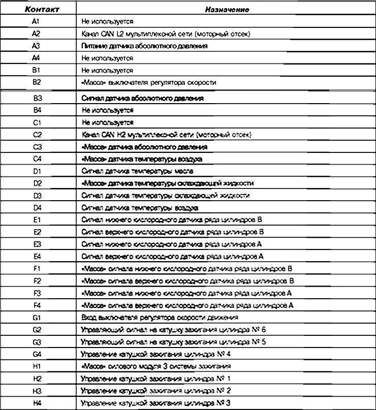
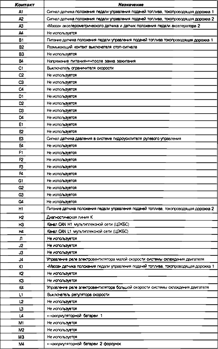
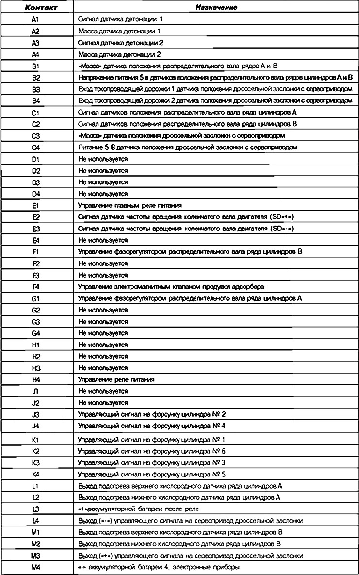
ECU contact assignment
Connector (A), 32-pin
Connector (B), 48-pin
Connector (C), 48-pin
Replacement of system elements
Operations of replacing, programming or reprogramming the ECU
The system can be programmed or reprogrammed using the RENAULT CLIP diagnostic tool connected to the diagnostic socket.
Connect the diagnostic tool (to the network or to the cigarette lighter).
Connect the charger (when (re)programming the ECU, the electric fans of the engine cooling system are automatically switched on).
Observe the specified coolant temperature values entered into the diagnostic tool prior to (re)programming.
Each time after programming, reprogramming or replacing the ECU, do the following.
Turn off the ignition.
Start and then stop the engine (to initialize the ECU) and wait 30 sec.
Turn on the ignition and use the diagnostic tool to perform the following operations:
Enter command VP010 "Enter VIN". Process the faults detected by the diagnostic tool. Clear the data from the ECU memory.
(This note was copied from the resource: www.Renaultbook.ru)
Perform programming of the crankshaft speed sensor and throttle valve opening angles (see "Configurations and programming").
Perform a road test, then repeat the scan tool check.
Warning! It is prohibited to carry out testing using an injection system ECU taken from a spare parts warehouse, since it cannot be used on another vehicle afterwards.
Operation of replacing the throttle body with servo drive
When replacing the throttle valve unit, it is necessary to program the throttle valve end positions using command RZ005 "Programming".
Warning! Never operate the vehicle without programming the throttle end positions.
Attention! Do not disconnect the battery for 30 minutes after completing the programming operation (if other work needs to be done on the vehicle). It is prohibited to use an ECU taken from a spare parts warehouse for testing, since it will then be impossible to install it on any other car.
Configurations and programming
ECU programming
The ECU can be configured automatically based on the sensors and additional equipment installed in the vehicle. Automatic configuration begins upon recognition of the presence of a special multiplex network frame.
Throttle valve programming procedure
Since the throttle valve with servo drive does not provide for the coordination of the actual value obtained on the basis of signals from the sensor conductive tracks and the mechanical position of the throttle valve, it is necessary to make a correction in the ECU. During the adjustment, the throttle valve opening and its reserve position are programmed, and the potentiometer amplifier is balanced. The programmed values are entered into the ECU memory. The stages of programming the extreme positions and storing the programmed values constitute the initialization of the throttle valve with servo drive. In addition, the throttle valve springs are checked.
Programming must be performed correctly at least once during the life of the vehicle, when the ignition is first turned on (initial initialization) and every time the ECU or throttle body with servo drive is replaced.
1. Switch on the ignition and wait at least 5 seconds without starting the engine: this will automatically adapt to the throttle position.
2. Turn off the ignition.
3. To memorize the programmed values by the ECU, wait before turning the ignition back on:
- at least 10 s with a cold engine (coolant temperature below 85°C),
- not less than 130 s with a hot engine (coolant temperature is greater than or equal to 90°C).
4. Turn on the ignition, start the engine and let it idle for 1 min to properly adapt to the air flow passing through the throttle body with servo drive.
A malfunction occurs and a command is issued to set the throttle valve to the reserve position:
- in case of cancellation of the automatic programming procedure (stage 1 above) in less than 5 s and in case of failure to complete step 4.
- in case of failure to complete step 4.
Programming must be done at re-initialization and each time the ECU or the throttle body with servo is replaced. Turn on the ignition. Start the engine and let it idle for 1 min to properly adapt to the air flow through the throttle body with servo.