
Examination
Crankcase ventilation system
1. There are no specific procedures for checking the crankcase ventilation system. If there are problems (sometimes determined by contamination of the air filter element), check that the hoses are clean and not blocked.
1. This is obvious. Mark the position of the hoses before disconnecting to avoid confusion during installation.
Emission control
1. An exhaust gas analyzer will be required (CO meter). The ignition system must be in good condition, the air filter element must be clean, and the engine must be in good condition.
2. Warm up the engine to normal operating temperature, then connect an exhaust gas analyzer in accordance with the manufacturer's instructions.
3. Accelerate the engine to 2500 rpm for approximately 30 seconds, and then let it idle and check the CO level (talk to Specifications in Chapter Maintenance). If the CO level corresponds to the data given in Specifications, the system is working correctly.
4. If the CO level is higher than specified in Specifications, try to check the effect of the Lambda sensor by disconnecting its wiring. If the CO level rises when the sensor is disconnected, then the Lambda sensor is OK and the fault is in the catalytic converter. If disconnecting the sensor does not affect the CO level, then the sensor is faulty.
5. If you have a digital voltmeter, you can measure the output voltage of the Lambda sensor. The voltage must alternate between the two limits: 625 - 1100 mV (rich mixture) and 0 - 80 mV (lean mixture).
6. Replace the Lambda sensor if it is defective.
Lambda sensor
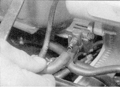
1. Jack up the front of the vehicle and place it on axle stands. Remove the engine undershield where present, then disconnect the sensor wiring.
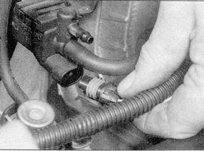
2a. Unscrew the sensor from the intake pipe.
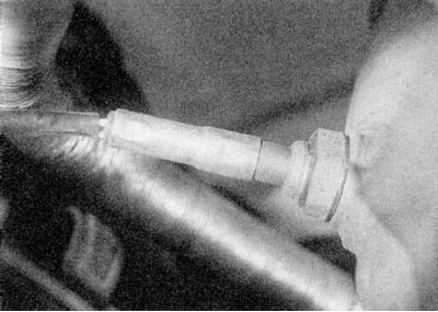
2b. Take it off (refer to illustrations).
3. Clean the threads in the downpipe and on the sensor.
4. Please note that if the wiring is broken, the sensor must be replaced. Don't try to restore it.
5. Apply high temperature anti-seize compound to the sensor threads. Screw the sensor in by hand and then fully tighten it.
6. Connect the sensor wiring, install the engine undershield and lower the vehicle to the ground.
Catalytic converter
1. The catalytic converter is replaced as part of the exhaust system. Refer to section Removing and installing the exhaust system from this Chapter.
Evaporative Emission Control
1. The solenoid valve should only be opened under the following conditions: the engine is warm, the throttle is not closed.
2. Warm up the engine to normal temperature, then turn it off. Attach a vacuum gauge (measuring range 0 - 1000 mbar) to the hose between the canister and the solenoid valve. Attach a voltmeter to the solenoid valve terminals.
3. Start the engine and let it idle. The pressure gauge should not show any vacuum, and there should be no voltage on the solenoid valve winding.
4. If the pressure gauge registered a vacuum, although the voltmeter does not show any voltage, the solenoid valve may be stuck open. Temporarily disconnect the hoses from the valve and blow it out to remove carbon particles.
5. If the voltmeter shows voltage at idle, then there is a malfunction in the wiring or computer.
6. Lightly press the accelerator. For a moment, voltage should appear at the valve terminals and a vacuum is registered.
7. If there is no vacuum even when voltage is present, then either there is a leak in the hoses or the valve does not open.
8. If voltage does not appear, then there is a malfunction in the wiring or computer.
Replacing the carbon adsorber
1. Temporarily remove the electronic fuel injection system control module from the right front of the engine without disconnecting the electrical wiring.
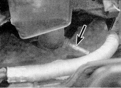
2. Disconnect and plug the hose from the top of the canister (refer to accompanying illustration).
3. Engage the handbrake, then jack up the front of the vehicle and place it on axle stands.
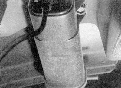
4. Turn away and remove fixing bolts between a forward bumper and a fairing of a wing, then remove an adsorber from an impellent compartment.
5. Be aware that the canister may contain liquid fuel and/or fuel vapor.
6. Install the new adsorber in the reverse order of removal. Make sure the hoses are connected correctly.
Solenoid valve replacement
1. Depending on the engine, the solenoid valve may be located in the following locations:
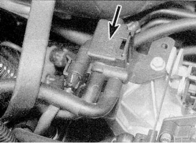
- a) E7J engine - on the top of the intake manifold, to the right of the throttle body (refer to accompanying illustration).
- b) K7M engine - at the right end of the intake pipeline
- With) F3R and F7R engines - on the front right side of the engine, on the same bracket with the fuel system control unit.
2a. Disconnect the hoses.
2b. Disconnect the multi-pin connector from the valve. Release the valve from fastenings, and remove it.
3. Install the new valve in the reverse order of removal. Make sure the hoses are connected correctly.
Replacement
Exhaust Gas Recirculation
1. Warm up the engine to normal operating temperature (the cooling fan should turn on), then turn it off.
2. Disconnect the wiring from the EGR solenoid valve located on the left end of the cylinder head.
3. Apply 12V power supply to the valve.
4. Disconnect the vacuum reservoir hose from the valve, then connect the vacuum pump and apply a vacuum of 300 mbar. Make sure the vacuum does not drop faster than 2 mbar per second.
5. Disconnect the vacuum pump, then start the engine and let it idle. Connect the vacuum pump and create a vacuum of 300 mbar; the engine should run erratically at idle. If this is not the case, the valve should be replaced, however note that Renault recommends cleaning the valve every 80,000 to 95,000 km (contact the head Maintenance).
Exhaust gas recirculation valve (K7M engine)
1. Unscrew and remove the rod between the front suspension domes.
2. Remove an inlet air line between the air filter and the case of a throttle, being guided by a part And this Chapter.
3. Disconnect the crankcase ventilation hose from the valve cover and move it to the side.
4. Disconnect the throttle cable from the throttle body and move it to the side.
5. Disconnect the vacuum hose from the EGR valve, then disconnect the wiring.
6. Turn away fixing bolts and get the valve from a head of the block of cylinders. Remove seal.
7. Install the new valve in the reverse order of removal, but use a new packing and tighten the mounting bolts as shown in Specifications effort.
Exhaust gas recirculation valve (F7R engine)
1. Disconnect the vacuum hose from the valve, then disconnect the wiring.
2. From the back of the valve, release the bracket that secures the steel pipe to the valve body.
3. Turn away two fixing bolts and remove the valve. Remove seal.
4. Install the new valve in the reverse order of removal, but use a new packing and tighten the mounting bolts as shown in Specifications effort.