
All diesel models are also designed to meet stringent emission requirements and are equipped with a crankcase ventilation system. In addition, some models can be equipped with a catalytic converter to reduce harmful emissions in the exhaust gases. To further reduce harmful emissions, there is an exhaust gas recirculation system.
Toxicity reduction systems operate as follows.
Petrol models
Crankcase ventilation system - E7J engine
1 - Inlet channel of the air filter; 2 - Hose connecting the valve cover with the air filter; 3 - Large limiter; 4 - Small limiter; 5 - Hose connecting the valve cover with the inlet pipeline; 6 - T-shaped connector; 7 - Inlet of the inlet pipeline; 8 - To the carbon adsorber
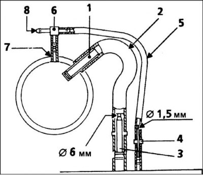
Crankcase ventilation system - K7M engine
1 - Cylinder head; 2 - Inlet pipeline; 3 - Crankcase ventilation hose to the air duct; 4 - Hose connecting the valve cover with the inlet pipeline; 5 - Hose of the carbon adsorber valve; 6 - T-shaped connector; 7 - Ventilation hose in the intake manifold; 8 - Air duct; 9 - Limiter with a diameter of 5 mm
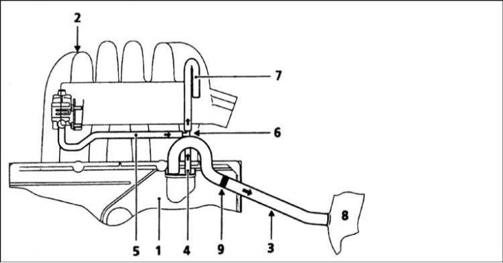
Crankcase ventilation system - F3R engine
1 - Inlet pipeline; 2 - Throttle body; 3 - Crankcase ventilation hose to the throttle body; 4 - Oil separator; 5 - Crankcase ventilation hose to oil separator
Crankcase ventilation system - F7R engine
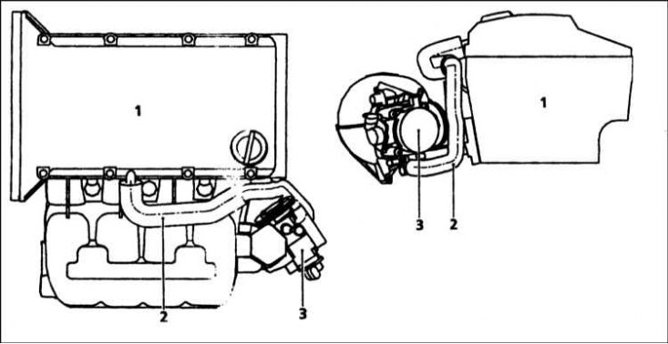
1 - Cylinder head; 2 - Crankcase ventilation hose to the throttle body; 3 - Throttle body
To reduce emissions of unburned hydrocarbons from the crankcase to the atmosphere, the engine is sealed and crankcase oil vapor is drawn from the inside of the crankcase through a wire mesh oil separator into the air intake duct, and is further combusted by the engine during normal combustion (refer to illustrations).
At high vacuum in the pipeline (idling, deceleration) gases will be sucked out of the crankcase. At low vacuum in the pipeline (acceleration, full throttle) gases are squeezed out of the crankcase by a relatively higher pressure in the crankcase; if the engine is worn, increased pressure in the crankcase (due to increased gas breakthrough) is the reason for the return of part of the flow in all conditions of the pipeline.
Crankcase breather hoses and restrictors must be cleaned periodically to ensure proper system operation.
Emission monitoring
To reduce the amount of pollutants that enter the atmosphere, all models are equipped with a catalytic converter in the exhaust system. The system is a closed loop type in which a lambda sensor in the exhaust system provides the fuel injection/ignition ECU with constant feedback, allowing the electronic control unit to adjust the mixture to provide the best possible conditions for the catalyst to operate.
The lambda sensor has a built-in heating element which is controlled by the ECU via the lambda sensor relay to quickly bring the sensor tip to effective operating temperature. The tip of the sensor is sensitive to oxygen and sends a voltage to the ECU that varies depending on the amount of oxygen in the exhaust gases; if the inlet air/fuel mixture is too rich, the exhaust gases are low in oxygen, the sensor sends a low voltage signal, the voltage rises, leaning the mixture and increasing the amount of oxygen in the exhaust gases. The maximum efficiency of the catalyst in neutralizing all major pollutants occurs when the fuel-air mixture is maintained in the chemically correct ratio for the complete combustion of gasoline (14.7 parts of air to 1 part of fuel). The sensor output voltage at this point changes over a wide range, the ECU uses the change in voltage as a signal to correct the air/fuel ratio by changing the fuel injection pulse width.
Evaporative recirculation control
Evaporative Emission System - E7J Engine
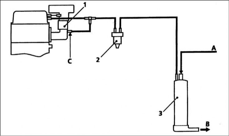
1 - Throttle body; 2 - Cleaning valve; 3 - Adsorber with activated carbon; A - Ventilation hose from the fuel tank; B - Breather; C - Vacuum behind the throttle
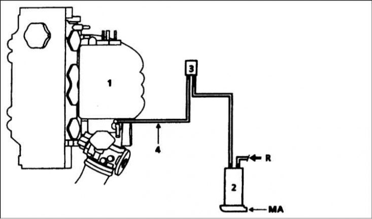
Fuel vapor recovery system - K7M engine

1 - Inlet pipeline; 2 - Adsorber with activated carbon; 3 - Cleaning valve; 4 - Recirculation pipe; 5 - Crankcase ventilation pipe; 6 - T-shaped connector of steam recirculation and crankcase ventilation pipes; 7 - Crankcase ventilation pipe; R - Pipe from the fuel tank; MA - Breather
Evaporative Emission System - F3R Engine (F7R similar)
1 - Inlet pipeline; 2 - Adsorber with activated carbon; 3 - Cleaning valve; 4 - Recirculation pipe; R - Pipe from the fuel tank; MA - Breather
To reduce the leakage of unburned hydrocarbons into the atmosphere, all models are also equipped with a fuel vapor recovery system (refer to illustrations). The fuel filler cap is sealed and the carbon canister is mounted on the front right side of the engine compartment. The charcoal canister collects vapors generated in the tank when the car is parked and stored there until they are removed (under ECU control of ignition and fuel injection systems) through the purge valve into the air intake duct, and then they are burned by the engine during normal combustion.
To ensure proper engine operation when the engine is cold and/or idling, and to protect the catalytic converter from being affected by a rich mixture, the purge control valve does not open until the engine is warm under load, the valve then opens to allow steam to pass through. into the intake tract.
Exhaust gas recirculation system - K7M 703 engine
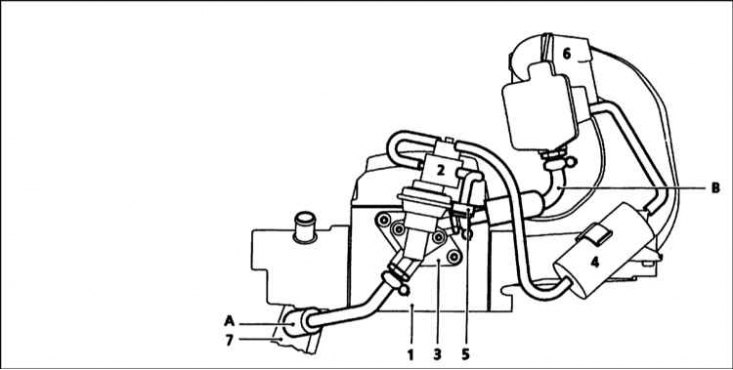
1 - Cylinder head; 2 - Solenoid valve for exhaust gas recirculation; 3 - Mount; 4 - Vacuum reservoir; 5 - Filter block; 6 - Inlet pipeline; 7 - Exhaust manifold
Exhaust gas recirculation system - F7R engine
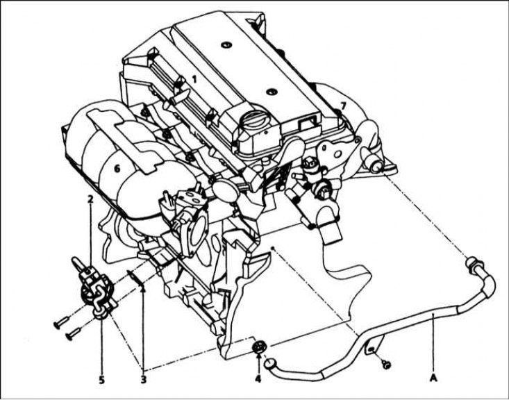
1 - Cylinder head; 2 - Solenoid recirculation valve; 3 - Seal; 4 - Bracket; 5 - Filter block; 6 - Inlet pipeline; 7 - Exhaust manifold; A - Pipe from the exhaust manifold to the exhaust gas recirculation valve; B - Pipe from the EGR valve to the intake manifold
This system is installed on the K7M and F7R engines and is designed to reduce the amount of nitrogen oxide in the exhaust gases, lowering the combustion temperature (refer to illustrations). This is achieved by feeding some of the exhaust gases from the intake ducts in the cylinder head back into the intake manifold and re-burning them. EGR valve (EGR) located on the left wall of the cylinder head on the K7M engine; and on the front of the engine, next to the throttle body, on F7R engines.
Diesel models
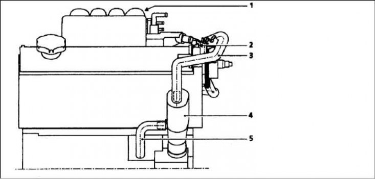
Typical crankcase ventilation system - F8Q 620 models
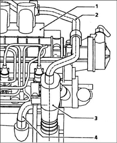
1 - Inlet pipeline; 2 - Hose to the inlet pipeline; 3 - Oil separator; 4 - Return tube to pallet
To reduce emissions of unburned hydrocarbons from the crankcase to the atmosphere, the engine is sealed and blow-by gases and oil vapors are drawn from the inside of the crankcase through a wire mesh oil separator into the intake port, and are further combusted by the engine during normal combustion (refer to illustrations).
The hoses of the system must not be clogged, since the minimum vacuum in the inlet pipeline will remain constant at all operating conditions of the engine.
Emission monitoring
To reduce the amount of pollutants emitted into the atmosphere, an uncontrolled catalytic converter is installed in the exhaust system. The catalytic converter works autonomously in the exhaust system and does not have a lambda sensor, as in petrol models.
Exhaust gas recirculation system - F8Q engine
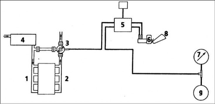
1 - Inlet pipeline; 2 - Exhaust manifold; 3 - Exhaust gas recirculation valve; 4 - Air filter; 5 - Electromagnetic channel for exhaust gas recirculation; 6 - Fuel pump microswitch; 7 - Vacuum pump; 8 - Load lever on the fuel pump; 9 - Vacuum brake booster
Exhaust gas recirculation system (EGR)
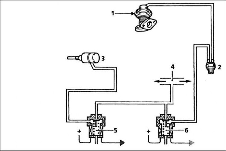
1 - EGR valve; 2 - Thermal valve; 3 - Vacuum fast idle speed activator; 4 - Vacuum between the vacuum pump and the brake booster; 5 - E / m valve for fast idle speed; 6 - E/m valve EGR
This system returns a small amount of exhaust gases to the intake duct, and then it is involved in the combustion process (refer to accompanying illustration), as a result, the level of nitrogen oxides in the exhaust gas, which is released into the atmosphere, is reduced.
The volume of circulating exhaust gases is controlled by the vacuum obtained from the vacuum pump of the brake booster, through an electromagnetic unit controlled by the preheat system. A vacuum controlled valve is mounted on the exhaust manifold.
On the F8Q 620 engine, the solenoid valve is controlled by a micro switch (which is also used to disable the preheat function), installed on the fuel pump (contact the head Engine electrical equipment). Power is supplied to the valve winding through a thermal switch mounted in the coolant temperature sensor.
On F8Q engines with a turbocharger, the solenoid valve is controlled by the electronic control module, which also regulates injection timing and fast idle speed. On the F9Q engine, the solenoid valve is controlled by the engine management system.
A thermal valve in the vacuum supply hose, or a control signal from the ECU, stops the vacuum supply until the engine has warmed up to normal operating temperature.
On F8Q engines with a turbocharger, the action of the solenoid valve depends on the following parameters: air temperature, coolant temperature, altitude, accelerator position, vehicle acceleration and engine speed. The power supply to the valve is interrupted in the following cases: air temperature is below 10°C, coolant temperature is below 40°C, engine speed is more than 3000 rpm. The power supply to the solenoid valve is cut off after 35 seconds of engine idling (at zero vehicle speed). As soon as the speed exceeds 40 km/h, the exhaust gas recirculation system starts working again.
On F9Q engines, the system is controlled directly by the engine management system.
Catalytic converter
Warning! To ensure long life and satisfactory performance of the catalytic converter, certain precautions must be taken. They are listed in Section Catalytic Converter - General Description and Precautions of this Chapter.