



Contents: Crankcase ventilation system 🠛 Branch before the throttle valve…🠛 Branch after the throttle valve block 🠛 Operating principle 🠛 Checking the purge of the absorber 🠛 Conditions for purging the absorber 🠛 Removal the absorber 🠛 Installation 🠛
Crankcase ventilation system
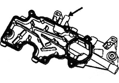
Note: The crankcase ventilation system box is located on the cylinder head cover.
 |
 |
 |
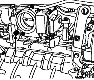
Crankcase ventilation system outlet (engines F4P - K4M) |
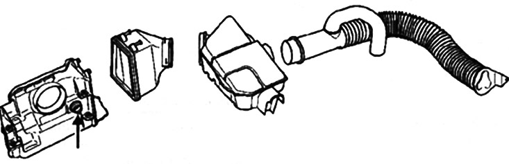
Crankcase ventilation system inlet (f4P - K4M engines)
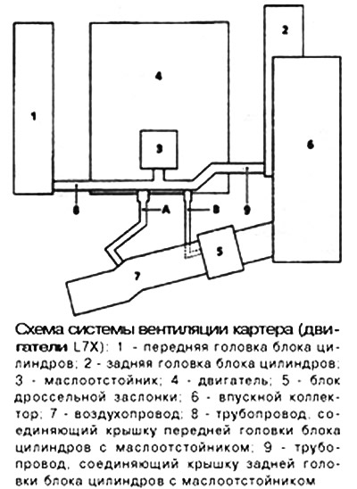
Branch before the throttle valve block
This branch is used at medium and high engine loads. The vapors are absorbed due to the vacuum created in the air duct 7.
Branch after the throttle valve block
This branch is used at low engine loads. The vapors are absorbed by the vacuum created between the throttle valve and the engine.
Caution! During normal operation, the vent hole must not be blocked.
Operating principle
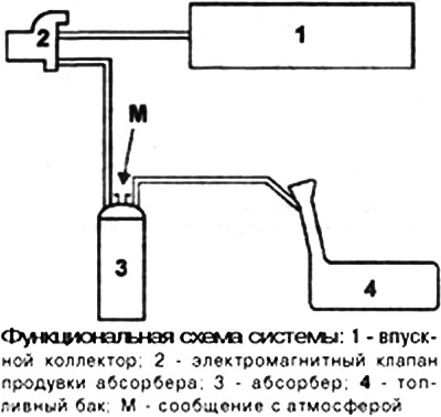
Communication with the atmosphere of the fuel tank is carried out through the fuel vapor absorber.
Material taken from an online portal Renaultbook.ru
Gasoline vapors are retained by activated carbon contained in the absorber.
The gasoline vapors contained in the absorber are eliminated by burning them in the engine.
To do this, the absorber is connected to the intake manifold via a pipeline and an electromagnetic valve. The electromagnetic valve is located on the right front mudguard cup on F4P, K4M, F5R engines and next to the power steering reservoir on the L7X engine.
The principle of operation of the electromagnetic valve is based on changing the flow cross-section (according to the cyclic opening degree signal generated by the injection system ECU).
The change in the cross-section of the fuel vapor passage channel in the electromagnetic valve occurs due to the balance between the magnetic field created when the supply current passes through the winding and the force of the return spring, which ensures the closing of the electromagnetic valve.
Checking the purge of the absorber
Malfunction of the system may result in unstable engine idling or spontaneous engine shutdown.
Make sure the system piping is connected correctly (see functional diagrams).
Check the condition of the pipes to the fuel tank.
Conditions for purging the absorber
The purge solenoid valve of the absorber is controlled (from contact C-E1 on K4M and F4P engines and from contact C-F4 on L7X engine) ECU, under the conditions listed below.
Engines F4P and K4M:
- coolant temperature above 55°C;
- air temperature above 10°C;
- the engine is not in idle mode;
- the specified load threshold has been reached;
- the throttle position sensor is not in the idle position.
L7X Engine:
- coolant temperature above 35°C;
- the time delay after launch is 20 sec.
When performing diagnostics using the on-board diagnostic system, purging the canister is not permitted.
It is possible to visually display the degree of cyclic opening of the canister purge solenoid valve using diagnostic tools, see the parameter "Degree of cyclic opening of the canister purge solenoid valve".
The solenoid valve is closed if the value is below 1.5%.
Removal the absorber
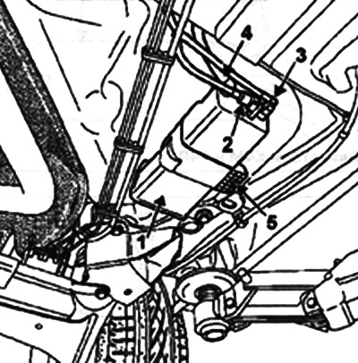
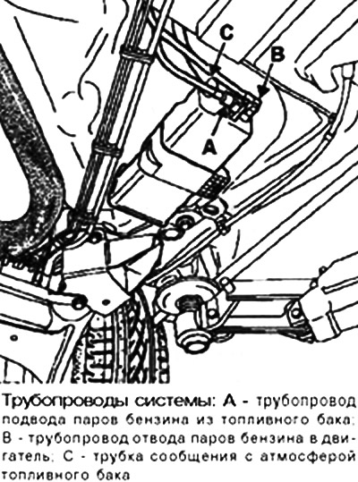
Absorber 1 is located above the left side of the fuel tank.
Disconnect:
- pipeline 2 supplying vapors from the fuel tank;
- pipe 3 for removing steam to the electromagnetic valve;
- tube 4 communication with the atmosphere.
Remove bolt 5 of the mount and the absorber.
Installation
Installation is carried out in the reverse order of removal.