
Examination
With coded electronics
1. The components of this system do not require any attention other than checking the condition of the hoses.
1. This is obvious. Mark the location of the hoses before disconnecting them to avoid confusion during installation.
Emission control
1. The system can only be accurately checked using a suitable exhaust gas analyzer (for diesel engines).
Catalytic converter
1. The catalytic converter is replaced as part of the exhaust system.
Exhaust Gas Recirculation
Note. The following procedure only applies to F8Q engines. Due to the need to use special Renault diagnostic equipment to check the valve on F9Q engines, entrust this work to a Renault workshop.
1. Start the engine and let it warm up to normal operating temperature (the cooling fan should turn on).
2. With the engine running at idle, disconnect the vacuum hose from the recirculation valve. After that, a click of the closing valve should be heard. If a click is not heard, proceed as follows.
3. Check for vacuum at the end of the vacuum hose to the recirculation valve. If a suitable pressure gauge is available, check that the pressure is less than 500 mbar. If vacuum is present, the recirculation valve is probably defective (pinched or broken diaphragm). If there is no vacuum, perform the following checks.
4. Check that all hose connections are secure.
5. Check the power supply to the valve coil.
6. Check the function of the thermal valve. This can be done by checking the passage of vacuum when the engine warms up to normal operating temperature. Shut off the engine and disconnect the thermal valve vacuum hoses from the recirculation valve and solenoid valve and check that air flows through the hoses. If this is not the case, the thermal valve is probably defective or the hoses are clogged.
7. Check the functioning of the microswitch of the exhaust gas recirculation system and the preheating system as described in Chapter Engine electrical equipment.
Exhaust Gas Recirculation System Components - F9Q Engine
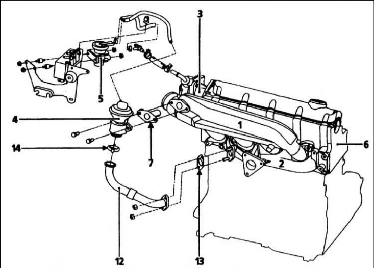
1 - Inlet pipeline; 2 - Exhaust manifold; 3 - Vacuum pump; 4 - Exhaust gas recirculation valve; 5 - Winding of the exhaust gas recirculation valve; 6 - Cylinder head; 7 - Fan; 12 - Steel pipe; 13 - Seal; 14 - Clamp
Replacement
Exhaust gas recirculation valve
1. The valve is located on the back of the engine and is attached to the exhaust manifold (engines F8Q 620) or to the intake manifold (turbocharged F8Q and F9Q engines) (refer to the accompanying illustration above). The valve is connected to another manifold through a metal pipe.
2. Disconnect the vacuum hose from the valve.
3. Turn away bolts of fastening and disconnect a pipe of the valve from the inlet pipeline or a final collector. Remove the gasket.
4. Unscrew the valve body from the manifold and remove the gasket. Remove the valve together with the pipe.
5. If a new valve is being installed, remove the mounting bolts or release the clamp and reposition the pipe on the new valve using a new gasket where applicable.
6. Install in reverse order, use new gaskets.
Solenoid valve (F8Q engines)
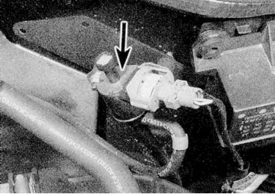
1. The valve is on a bracket attached to the bulkhead of the engine compartment (refer to accompanying illustration).
2. Disconnect the electrical connector and vacuum hoses from the valve.
3. Turn away fixing nuts and get the valve together with an arm.
4. Install in reverse order, making sure the vacuum hoses are securely connected.
Thermal valve (F8Q engines)
1. The thermal valve is located in the coolant hose, in the left front corner of the cylinder block.
2. To remove the valve, simply disconnect the electrical connector and unscrew the valve from the hose.
3. Install in the reverse order of removal. Check for coolant leaks and, if necessary, top up the coolant level.
Altimeter sensor (altitude meter) (F8Q engines)
Note. On F8Q engines with a turbocharger and on F9Q engines, the sensor is integrated in the electronic control module and cannot be separated from it.

1. The sensor is located in the engine compartment on the front left wheel arch, behind the headlight (refer to accompanying illustration).
2. Disconnect a socket of electroconducting from the gauge, then turn away fixing nuts and get the gauge.
3. Install in reverse order.
Replacing the fuel pump microswitch (automatic exhaust gas recirculation switch) - F8Q engines
4. The removal and installation of the switch is obvious, but please note that the switch must be adjusted in the end. To do this, contact a Renault workshop. See chapter for details Engine electrical equipment.