
Removing
5. Disconnect the wire terminal from the battery «masses» (-).
Attention! This removes the recorded information from some devices, and the security code from the radio, as well as all automatic settings on the radio. Therefore, before disconnecting the battery, read the chapter «Battery - removal and installation».
6. Disconnect the large diameter wires from the terminals on the back of the generator (terminal B+) and thin diameter (terminal D+) (see arrows in illustration).
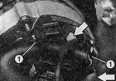
16.6 Disconnect the large diameter wires from the terminals on the back of the generator (terminal B+) and thin diameter (terminal D+) (see arrows). 1 - alternator mounting bolts
Vehicles with a 1.4-/1.6-liter petrol engine (E7J/K7M)
7. Mark with paint the position of the right front wheel on the hub. This will allow the assembly to set the balanced wheel in its original position.
8. Loosen the wheel bolts. In this case, the car must be on the ground.
9. Install the front of the car on the goats and remove the front wheel.
10. Loosen the tightening of the three bolts 1 fastening the power steering pump (see illustration). It is not necessary to completely unscrew the bolts.
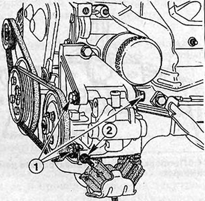
16.10 Loosen the three bolts 1 fastening the power steering pump
11. Loosen the tension of the ribbed belt by loosening the nut 2 (see illustration 16.10).
12. Remove the drive V-belt from vehicles with air conditioning.
13. Unscrew the clamping bolt 3, unscrew the support bolt 4, turn the generator towards the engine and remove the V-belt (see illustration).
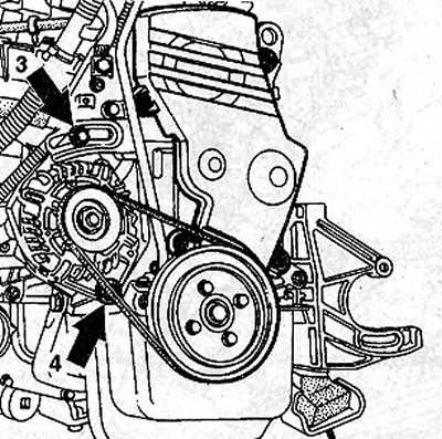
16.13 Unscrew the clamping bolt З, unscrew the support bolt 4, turn the alternator towards the engine and remove the V-belt
14. Remove the support bolt 4 through the hole 5 in the right wheel arch (see illustration).
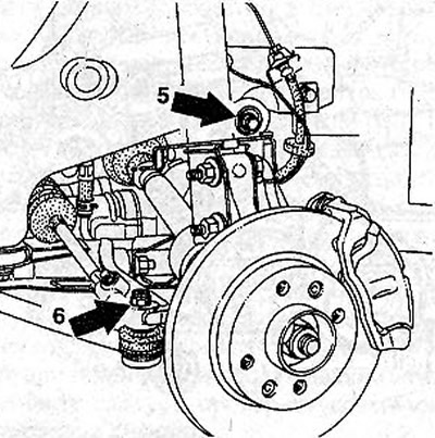
16.14 Remove the support bolt 4 through the hole 5 in the right wheel arch
15. Unscrew the nut 6 of the ball joint finger of the tie rod end and press the finger out of the lever on the steering knuckle (see illustration 16.14).
16. Support the transverse arm so that the axle shaft does not sag after disconnecting the shock absorber.
17. Unscrew the bolts 2 fastening the upper suspension strut support to the mudguard (see illustration). To facilitate subsequent installation, it is recommended to circle the places where the bolt heads fit on the mudguard with a marker or felt-tip pen.
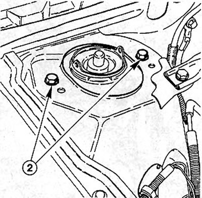
16.17 Unscrew the bolts 2 fastening the upper suspension strut support to the mudguard
18. Lower the rack together with the steering knuckle and the hub down as far as possible, while avoiding bending the drive axle. This is necessary to remove the generator through the wheel arch of the removed right wheel.
19. Remove the generator.
Installation
20. Put the generator in place and secure with bolts 3 and 4, without performing their final tightening (see illustration 16.13).
21. Install a new ribbed drive belt for the generator and power steering pump.
22. Connect large diameter wires to the generator terminals (terminal B+) and thin diameter (terminal D+).
23. Fix the top support of an amortization rack on a mudguard, having used tags put at removal. Tighten the rack mounting bolts with a force of 30 Nm.
24. Insert the ball joint pin of the tie rod end into the hole on the tie rod arm and screw a new self-locking nut onto the pin with a torque of 35 Nm.
25. Establish a wheel, being guided by labels made before removal, and screw in wheel bolts. Do not grease bolts.
26. Lower the vehicle onto the wheels and tighten the wheel bolts in a criss-cross pattern to 90 Nm.
Vehicles with a 1.4-/1.6-liter petrol engine (K4J/K4M)
27. Mark the position of the right front wheel on the hub with paint. This will allow the assembly to set the balanced wheel in its original position.
28. Loosen the wheel bolts. In this case, the car must be on the ground.
29. Install the front of the car on the goats and remove the front wheel. •
30. Remove, if necessary, the fender liner of the right wheel arch by unscrewing the mounting bolts.
31. Remove the alternator ribbed belt.
32. Disconnect the holder of the hydraulic booster pipeline near the radiator blower fan and press the fan a little to the side, if necessary.
33. Disconnect the large diameter wires from the terminals on the back of the generator (terminal B+) and thin diameter (terminal D+) (see illustration 16.6).
34. Unscrew the three bolts 1 and remove the generator 2 (see illustration).
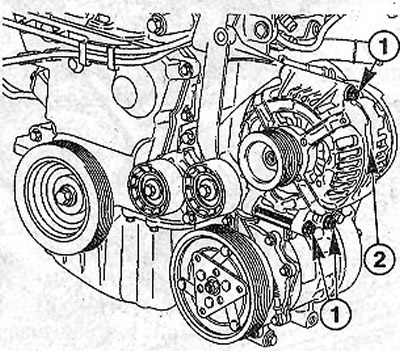
16.34 Unscrew the three bolts 1 and remove the alternator 2
Installation
35. Put the generator in place and secure it with three bolts with a torque of 21 Nm.
36. Lay the ribbed belt.
37. Install, if necessary, the radiator blower fan to its original position and secure the power steering pipeline in the holder.
38. Connect large diameter wires to the generator terminals (terminal B+) and thin diameter (terminal D+).
39. Install, if removed, the fender liner of the right wheel arch and secure it with bolts.
40. Establish the right wheel, being guided by labels made before removal, and screw in wheel bolts. Do not grease bolts.
41. Lower the vehicle onto the wheels and tighten the wheel bolts in a criss-cross pattern to 90 Nm.
Vehicles with a 2.0 liter petrol engine (113 hp)
Removing
42. Remove the ribbed alternator drive belt.
In order to unscrew the generator support bolt, it is necessary to remove the ignition coils together with the bracket.
43. Unscrew the mounting bolts in sequence 1-3 and move the bracket down (see illustration).
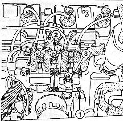
16.43 Unscrew the mounting bolts in the sequence 1-Move the bracket down
44. Unscrew the top and bottom bolts of fastening of the generator and remove it.
Installation
45. Put the generator in place and secure with bots.
46. Install a new ribbed belt and tension it.
47. Connect a large diameter wire to the generator terminal (terminal B+). Thin wire (terminal D+) connects to the connector.
48. Replace the bracket and ignition coils.
Vehicles with a 2.0 liter 16 valve petrol engine (150 hp)
Removing
49. Remove the front part of the right wheel arch liner.
50. Disconnect the adsorber hose and unscrew the bolts securing the injection system control unit to the bracket (see arrows in illustration). Place the control unit on the engine without disconnecting the wires from it.
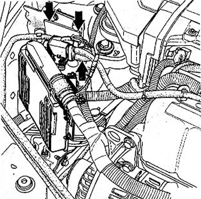
16.50 Disconnect the adsorber hose and unscrew the bolts securing the injection system control unit to the bracket (see arrows)
51. Remove the ribbed belt by securing the belt tensioner with a suitable pin.
52. Remove the pin and release the belt tensioner.
53. Unscrew the bolts D and E and remove the belt tensioner (see illustration). When unscrewing the bolt E, make sure that its gasket does not fly off and does not get between the engine and the tensioner.
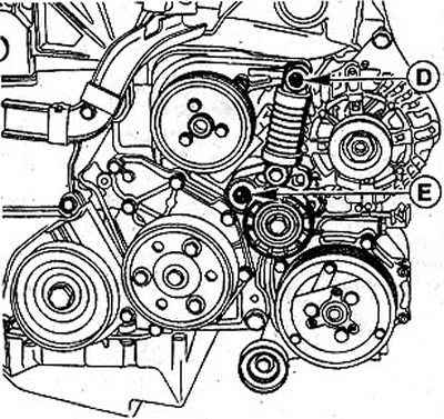
16.53 Unscrew bolts D and E and remove the belt tensioner
54. Disconnect the rear side of the generator thick wire (terminal B+) section and thin wire (terminal D+).
55. Disconnect the power steering reservoir from the mounting bracket and set it aside without disconnecting the hoses from the reservoir.
56. Unscrew bolts of fastening of the generator and remove it. To unscrew the generator bolts, you need a hex socket head and a wrench about 20 cm long.
Installation
57. Reinstall the generator.
58. Attach the power steering reservoir to the bracket.
59. Replace the ribbed belt tensioner and tighten it with the following torques:
- bolt D - 25 Nm;
- bolt E - 65 Nm.
Don't forget to put a washer on bolt E.
60. Install a new ribbed belt.
61. Connect the hose to the adsorber and fix the fuel injection system control unit on the bracket.
62. Connect to the generator electrical wires.
63. Install the removed part of the wheel arch liner.