
Removing the engine down
Required special tool
- B. Vi 31-01 Pins for knocking out elastic pins.
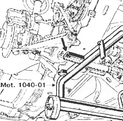
- Mot. 1040-01 Trolley for removal and installation of the power unit.
- Mot. 1202 Pliers for flexible clamps.
- Mot. 1311-06 Tool for removing fuel lines.
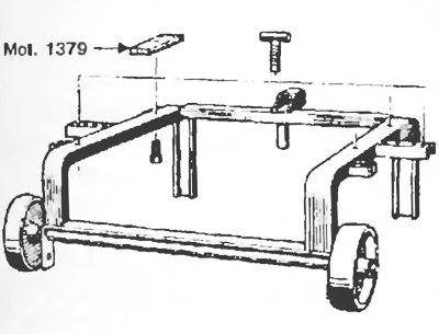
- Mot. 1379 Device for fixing the engine on the subframe.
- T. Av. 476 Puller for pressing ball joint pins.
- T. Av. 1233-01 Rod for bearing installation.
Tightening torques, Nm
- Bolts of fastening of a shock-absorber rack to a rotary fist: 180.
- Tie rod end ball stud nut: 37.
- Subframe front mounting bolts: 62.
- Rear subframe bolts: 105.
- Bolts of fastening of the holder of a cover of the internal hinge of a shaft of a drive of the left forward wheel: 25.
- Wheel bolts: 90.
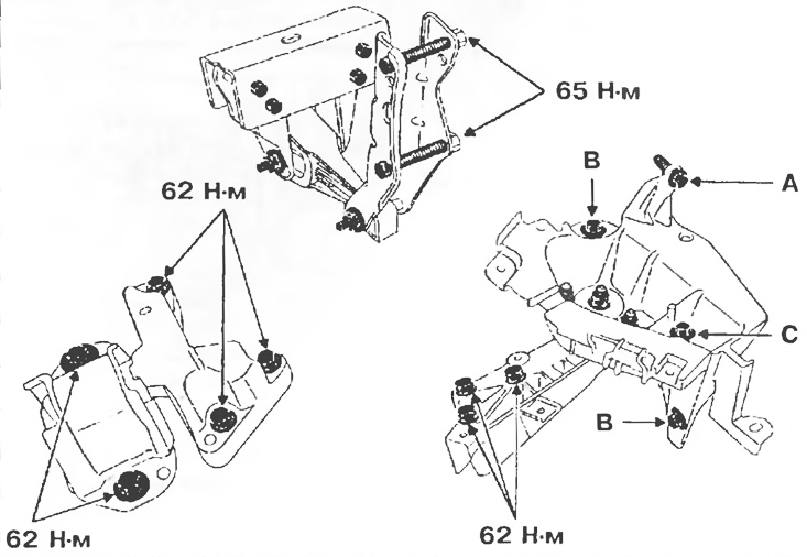
- Nuts for fastening the elastic cushion on the bracket of the left support of the engine pendulum suspension: 62.
- Bolts for fastening the front right support of the pendulum suspension to the engine: 62.
- Bolts for fastening the front right support of the pendulum suspension to the body: 62.
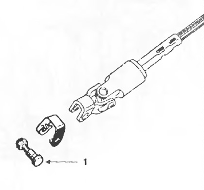
- Steering shaft universal joint yoke bolt: 25.
Removing
1. Place the vehicle on a two post lift.
2. Disconnect:
- battery;
- electrical connectors from the engine compartment switching unit and adjacent electrical appliances.

Pic. 2.2
3. Drain:
- fluid from the cooling system (disconnect the outlet hose from the radiator);
- gearbox oil (if necessary);
- engine oil (if necessary).
4. Remove:
- battery;
- wheels;
- air inlet;
- fastening details of the upper radiator support;
- expansion tank, fix it on the engine;
- power steering reservoir, secure it to the engine.
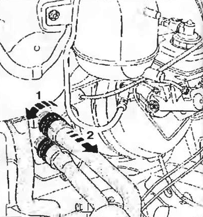
5. Disconnect:
- throttle cable;
- absorber hose;
- vacuum brake booster hose,
- heater radiator hoses;
- oxygen sensor connector;
- fuel pipelines.
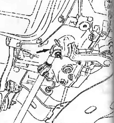
6. Turn out:
- bolts of fastening of a shock-absorber rack to a rotary fist;
- bolt of fastening of connection of a plug of the cardan hinge of a steering shaft.
Pic. 2.3
Attention! Features of vehicles equipped with a driver's airbag.
To prevent damage to the slip ring under the steering wheel, the following rules must be observed:
- before disconnecting the steering column and the steering mechanism, lock the steering wheel in the straight ahead position with a special device, and the steering wheel must remain locked during the entire time of work;
- if in doubt about the correct centering of the contact plate, remove the steering wheel and center it.
7. Remove:
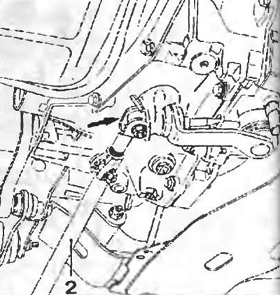
- two subframe amplifiers;
- a bolt of fastening of mass tires from a body;
- the nuts of the studs of the exhaust pipes of the exhaust system will work out, gases.
8. Disconnect the gear shift rod:
- from the selector lever in front of having previously displaced the protective cover;
- from the shift lever, having removed the central heat shield first.
9. Pull the rod to the rear of the car.
Pic. 2.4
10. Fit fitted Mot. 1379 onto the subframe and use a threaded rod to unload the bracket for the right engine mount.
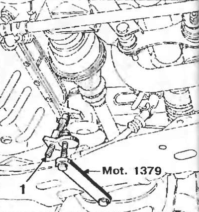
Pic. 2.5
11. Attach the trolley Mot 1040-01 to the bottom of the subframe, place the shims Mot. 1379
12. Place a piece of wood between the gearbox and subframe.
Bogie hole pattern Mot. 1040-01 (pic. 2A dimensions in mm)
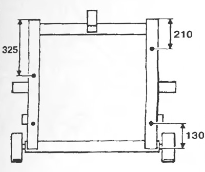
Pic. 2.6a
Pic. 2.6b
13. Remove:
- a nut of fastening of an arm of a pendulum suspension bracket of a transmission, then by means of a bronze punch knock out a pin of fastening of a support of a pendulum suspension bracket;
- bolts of fastening of an arm of a pendular suspension bracket to the engine.
14. Lower the lift until the cart wheels are in contact with the floor.
Pic. 2.7
15. Turn away four bolts of fastening of a stretcher.
16. Remove the power unit by lifting the body up.
Attention! Never place the engine on a sump, as this may damage the oil pump.
Installation
1. Use tool T. Av. 1233-01 in order to correctly position the power unit relative to the body.
2. Install in the reverse order of removal.
3. Tighten the bolts and nuts securing the swing arm brackets to the recommended torque (pic. 2.8).
4. Fill the driveshaft spring pin holes with Rhodorseal 5661.
5. Press the brake pedal several times to bring the brake pistons into position.
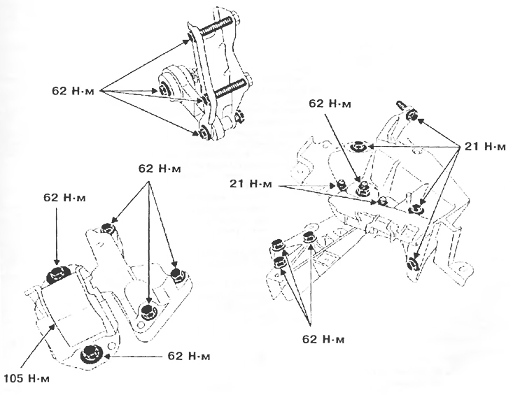
Pic. 2.8
6. Do:
- gearbox oil filling (if necessary);
- engine oil filling (if necessary);
- filling with coolant and removing air from the cooling system (see chapter «Maintenance» chapter «Filling coolant and bleeding»).
Removing the engine up
Necessary special tools and equipment
- B. Vi 31-01 Set of three rods for extracting elastic pins.
- Mot. 1202 Pliers for flexible clamps.
- Mot. 1273 Belt tensioner.
- Mot. 1311-06 Tool for removing fuel lines.
- Mot. 1379 Device for fixing the engine on the subframe.
- T. Av. 476 Puller for pressing ball joint pins tal.
Tightening torques, Nm
- Brake caliper guide pins: 40.
- Bolts of fastening of a shock-absorber rack to a rotary fist: 180.
- Bolts of fastening of the holder of a cover of the internal hinge of a shaft of a drive of the left forward wheel: 25.
- Wheel bolts: 90.
- Bolts for fastening the left support of the pendulum suspension of the engine to the gearbox: 62.
- Bolt and nut for fastening the left support of the engine pendulum suspension to the body: 21.
- Bolts of fastening of a pillow of the right support of a pendular suspension bracket of the engine to the engine: 62.
- Bolts for fastening the pillow of the right support of the pendulum suspension of the engine to the body: 62.
Removing
1. Place the vehicle on a two post lift.
2. Disconnect:
- battery;
- electrical connectors from the engine compartment switching unit and adjacent electrical appliances.
3. Drain:
- fluid from the cooling system (disconnect the outlet hose from the radiator);
- gearbox oil;
- engine oil (if necessary).
Pic. 2.9
4. Remove:
- battery;
- hood;
- wheels;
- air inlet;
- expansion tank, attach it to the engine.
5. Remove (left-hand side):
- a bolt of fastening of a floating bracket of a brake and fix it on a spring of a shock-absorber rack;
- three bolts of fastening of the holder of a cover of the internal hinge of a power shaft to a transmission;
- press the ball joint pin of the tie rod end out of the steering knuckle using a puller T. Av. 476;
- shock absorber mounting bolts to the steering knuckle.
Tilt the steering knuckle to disengage the drive shaft from the transmission.
6. Remove (Right side):
- elastic pins of the drive shaft using rods B. Av. 476;
- a bolt of fastening of a floating bracket of a brake and fix a bracket on a spring of a shock-absorber rack;
- press the ball joint pin of the tie rod end out of the steering knuckle using a puller T. Av. 476;
- shock absorber mounting bolts to the steering knuckle.
7. Deviate a rotary fist to disconnect a power shaft from a transmission.
8. Turn out a bolt of fastening of the mass tire (from the gearbox side).
9. Disconnect draft of a drive of a gear change from the lever of a choice of transfers, having displaced previously a protective cover.
Pic. 2.10
10. Turn away, without removing, a bolt and turn out a bolt In jet thrust.
Pic. 2.11
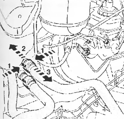
11. Disconnect:
- throttle cable;
- absorber hose;
- vacuum hose of the vacuum brake booster;
- hoses between the radiator and to the cylinder block jacket on the block side;
- front end radiator hoses (with plastic pic. 2.12a, or metal pipes - 2.126).
Pic. 2.12a
Pic. 2.12b
12. Disconnect:
- connectors for the oxygen sensor and the electric fan of the engine cooling system;
- fuel lines.
13. Remove:
- computer mounting bracket;
- power steering tube holders located on the engine;
- power steering pump drive belt;
- power steering pump drive pulley;
- power steering pump mounting bolts.
14. Release the power steering pump.
15. Attach the hoist hooks to the motor lifting eyes.
Pic. 2.13
16. Remove:
- bracket on the side of the gearbox.
Pic. 2.14
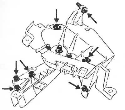
- bolts of fastening 2 elastic pillows of the engine 1.
17. Mark position of an elastic pillow of the engine 1 concerning a body.
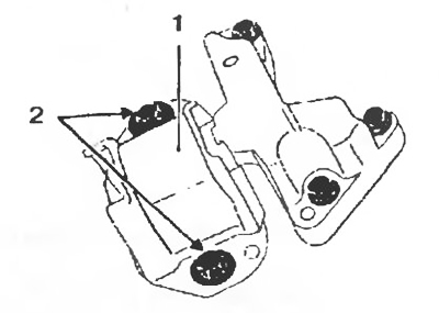
Pic. 2.15
18. Remove the power unit by first removing the power steering pump from the engine compartment and taking measures to protect the radiator from damage.
Attention! Never place the engine on a sump, as this may damage the oil pump.
Installation
1. Install in the reverse order of removal.
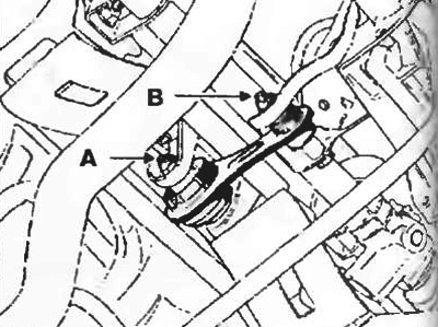
2. Tighten the pendulum suspension bracket bolts to the specified torque and in the following order:
- screw A, torque 21 Nm
- screw B, with a torque of 21 Nm;
- screw C, with a torque of 21 Nm.
3. Fill the driveshaft spring pin holes with Rhodorseal 5661.
4. Press the brake pedal several times to bring the brake pistons into position.
Pic. 2.16
5. Install the power steering pump drive belts.
6. Do:
- filling the gearbox with oil;
- engine oil filling (if necessary);
- filling with coolant and removing air from the cooling system (see chapter «Maintenance» chapter «Filling coolant and bleeding»).
Installing the engine on the base plate
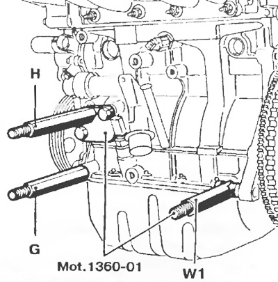
1. To install the engine on the base plate, screw the rods H, G, and W1 into the engine block so that they match the holes 10, 8, 4 in the base plate.
Note. Kit Mot. 1360-01, consisting of rod W1 and plate H1, is an addition to base plate Mot. 792-03.
Pic. 2.17
2. Tighten the motor stud nuts.
Note. Before screwing the rod into the engine, remove the following components and parts:
- - drive belts for additional equipment;
- - generator with bracket;
- - power steering pump;
- - the oil dipstick guide.