Technical data
1. Cylinder head
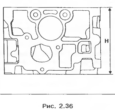
Cylinder head height, mm:
- nominal H = 118;
- repair H = 117.8.
The maximum allowable deformation of the mating surface, mm: 0.05.
Combustion chamber volume with valves and spark plug, cm3: 27,68 ± 0,65
The maximum allowable difference in the volume of combustion chambers in one head, cm3: 0,8.
2. Valve guides
Inner diameter, mm: 6+0,18.
Outer diameter of the guide sleeve, mm:
- nominal: 11:
- repair: 11.2.
Attention! The intake and exhaust valve guides have valve stem seals that must be replaced each time the valve train is disassembled.
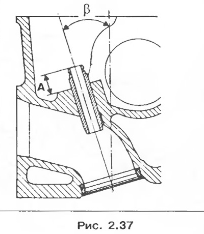
The inclination of the guide bushings of the intake and exhaust valves: P = 17.50°.
The position of the guide bushings of the intake and exhaust valves relative to the lower support ends of the valve springs, mm: A = 15±0.15.
3. Valve springs
Free length, mm: 43.
Length under load, mm:
- 240 N±1.35 37;
- 483 N±3 31
The length of the spring at full compression of the coils, mm: 25.6.
Wire diameter, mm: 3.90
Inner diameter, mm: 20.2.
4. Valves
Rod diameter, mm:
- intake valve: 5.98-0,015
- exhaust valve: 5.97-0,015
Chamfer Angle:
- intake valve: 120°;
- outlet valve: 90°.
Head diameter, mm:
- intake valve: 32.88±0.12;
- exhaust valve: 29.88±0.12.
5. Valve seats
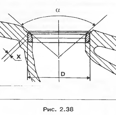
Chamfer Angle:
- inlet valves α = 120°,
- exhaust valves α = 90°.
Seat chamfer width, mm:
- intake valves X = 1.7±0.1;
- exhaust valves X = 1.7±0.1.
Seat outer diameter D, mm:
- intake valves 33.5+0,05+0,034;
- exhaust valves Z0.5+0,05+0,034.
6. Camshaft:
- axial clearance, mm: 0.07-0.148;
- number of bearings: 5.
7. Parts to be replaced when removed:
- all gasket seals;
- valve guides;
- camshaft pulley bolt;
- cylinder head bolt.
Disassembly
1. Remove the cylinder head (see section «Cylinder head gasket»).
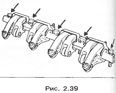
2. Remove the bolts securing the rocker arms and the axis of the rocker arms, having previously marked the position of the rocker arms on it.
3. Remove:
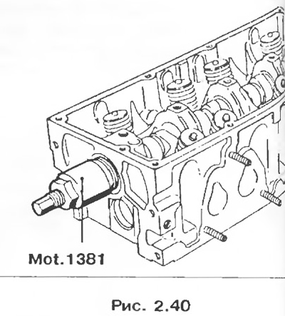
- camshaft gear pulley.
- camshaft seal using tool Mot. 1381.
4. Turn away bolts of fastening of a persistent flange of a camshaft.
5. Remove the camshaft.
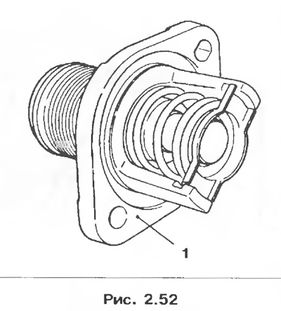
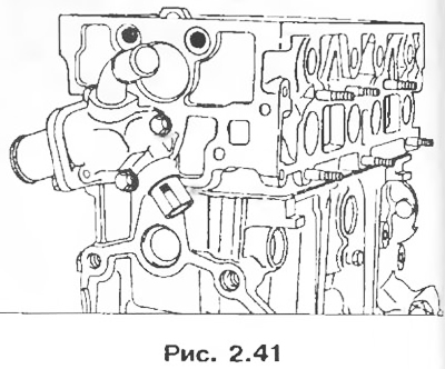
6. Remove the thermostat housing.
7. Remove the spark plugs.
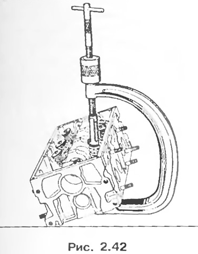
8. Remove the valve springs using the special tool.
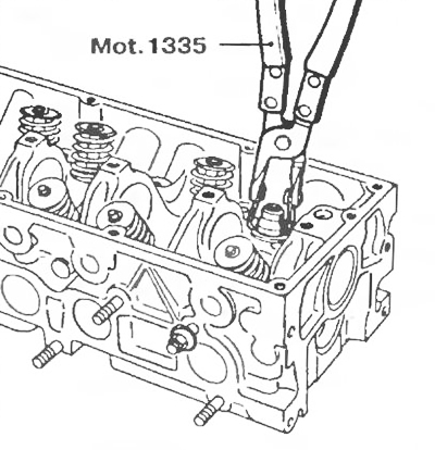
9. Remove the crackers, upper spring plates, valves, valve stem seals using special pliers Mot. 1335.
10. Clean the cylinder head and check the deformation of the mating surface (see section «Cylinder head gasket»).
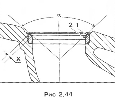
Valve seat grinding
Inlet valves X = 1.7±0.1; α = 120°.
Seat face 1 is ground with a 31°cutter, reduce the width of the face by grinding face 2 with a 75°cutter until width X is obtained.
Exhaust valves X = 1.7±0.1; α = 90°.
Seat face 1 is ground with a 46°cutter, reduce the width of the face by grinding face 2 with a 65°cutter until width X is obtained.
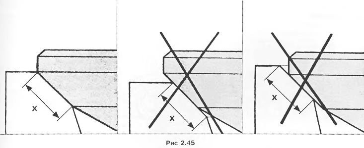
Attention! Check the correct fit of the valve to its seat (pic. 2.45).
Assembly
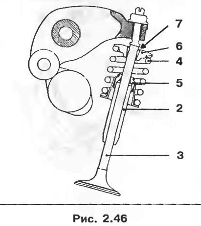
1. Insert new valves 3 and lightly lap each valve into its seat.
2. Thoroughly wash and label all parts, then proceed with assembly.
2. Lubricate all parts with engine oil.
3. Put on the valve guides 2 new valve stem seals 5.
4. Alternately install new valves 3, springs 4 (same for intake and exhaust valves) and top cymbals 6
5. Compress the springs.
6. Install crackers 7 (same for intake and exhaust valves).
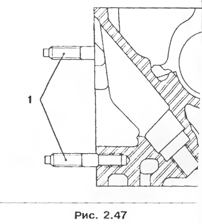
Note. Screw new studs 1 into the cylinder head and apply one drop of sealant.
Loctite Frenetanch. New cylinder heads are supplied from the spare parts warehouse complete with valves.
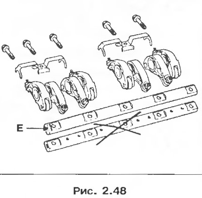
7. Check up a condition of surfaces of rollers and bolts of yokes. Make sure that the lubrication holes of the cams and the heels of the rocker arms are not clogged. Replace worn parts. Install the rocker shaft so that the E mark faces the timing gear.
8. Lubricate the camshaft with engine oil. Install the shaft into the cylinder head. Replace the camshaft thrust flange and secure it with the locking plate (without applying Loctite sealant to its mounting bolts).
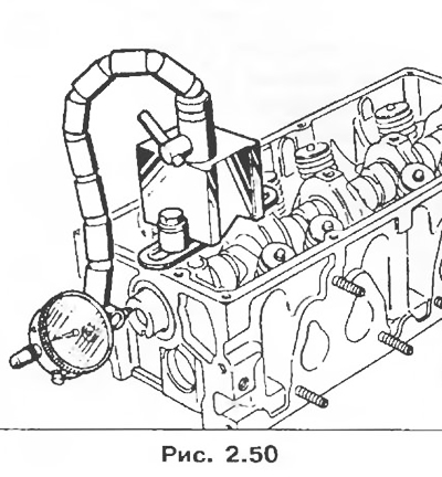
9. Install the magnetic bolt tightener.
10. Make sure that the axial clearance does not exceed 0.07-0.148 mm.
11. Remove the thrust flange stop plate bolts, apply one drop of Loctite Frenetanch to each, then install and tighten the bolts.
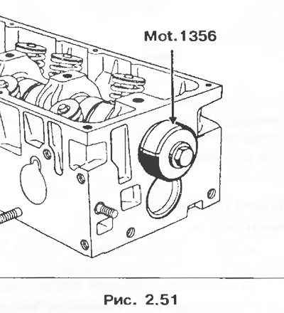
12. Install the oil seal using tool Mot.1356. This device allows you to shift the fit of the working edge of the oil seal on the camshaft.
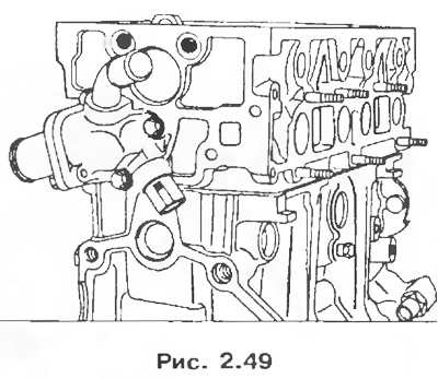
13. Install thermostat assembly. Apply Loctite 518 to flange 1 and to the thermostat housing located on the cylinder head.