
Table 2.5
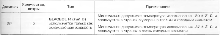
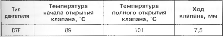
Table 2.6
Thermostat
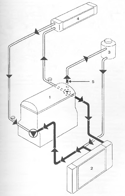
Pic. 2.81. Cooling system diagram:
1 - Engine;
2 - Radiator;
3 - Expansion tank, constantly removing air from the cooling system;
4 - Heater radiator;
5 - Calibration hole 3 mm.
The inclusion of a high speed of electric fans is carried out by the injection computer, at a coolant temperature above 99°C. Electric fans are switched off at temperatures below 96°C. Brown expansion tank valve (calibration pressure 1.2 bar).