
Technical data
1. Pistons
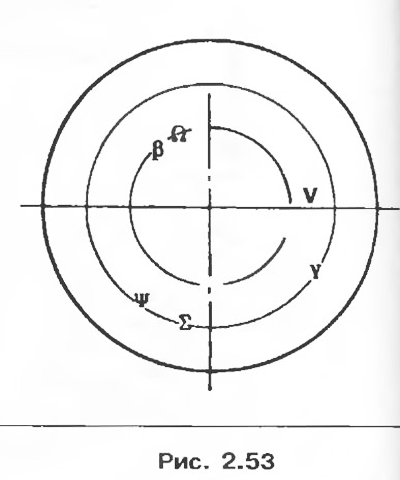
Skirt shape (*)
- β model (*)
- Ψ week of production (*)
- Σ index of modifications *)
- Y marking of size groups (table 2.1.)
- V Direction of installation of the piston towards the flywheel
(*) not used for after-sales service.
Table 2.2. Selection of pistons for cylinder liners
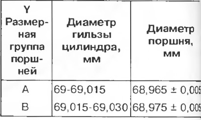
The piston diameter should be measured at a distance of A = 40 mm.
2. Cylinder liners
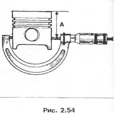
Attention! Be sure to observe the selection of diameters of pistons and cylinder liners. The selection is determined by the position of the holes T in relation to the mating surface of the cylinder head. The position of these holes makes it possible to select the tolerances of the cylinder liners in their nominal size group and therefore the piston diameters corresponding to these tolerances (table 2.1)
Note. The marking contains: 1 and 2 designation of the size group of pistons A or B; The T position of the holes indicates the size group for each cylinder.
Repair dimensions: the diameter of the cylinder liner and piston is increased by 0.25 mm.
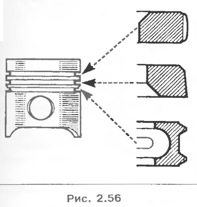
3. Piston rings
Thickness, mm:
- upper compression ring 1.47-1.49;
- lower compression ring 1.47-1.49;
- oil scraper ring 2.47-2.49.
4. Connecting rods
Axial clearance of the lower head of the connecting rod, mm: 0.21-0.453.
Table 2.3
5. Crankshaft
- Number of main bearings 5;
- Axial clearance, mm: 0.06-0.235.
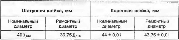
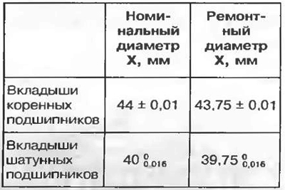
6. Crankshaft main bearing caps
Installation direction:
- Install the bearing shells 1-2-3-5 so that the grooved shells A are on the cylinder block, and the non-groove shells B are on the bearing caps.
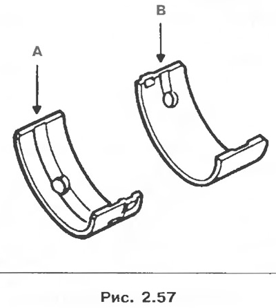
For bearing 3, a liner is installed (U-shaped), made as one piece with persistent half rings; the grooved liner C is mounted on the cylinder block, and the liner without groove D is mounted on the bearing cap.
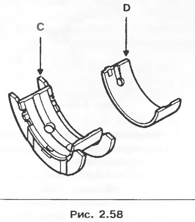
Table 2.4. Nominal and overhaul dimensions of main and connecting rod bearing shells
Parts to be replaced when removed
All seals and gaskets.
Metal tube of the cooling system.
Flywheel bolts.
Connecting rod cap bolts.
Crankshaft mounting bolts.
Disassembly
1. Remove the power unit.
2. Remove the cylinder head (see section «Cylinder head gasket»),
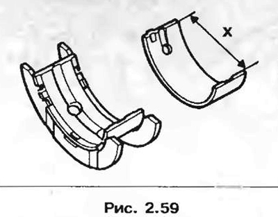
3. Remove:
- clutch mechanism and driven disc;
- engine flywheel by locking it with tool Mot. 582-01.
4. Remove the oil pan with gasket (silicone sealant for gaskets or metal-plastic gaskets are available for after-sales service).
5. Remove the timing gear pulley.
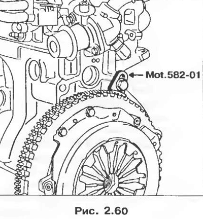
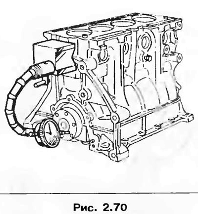
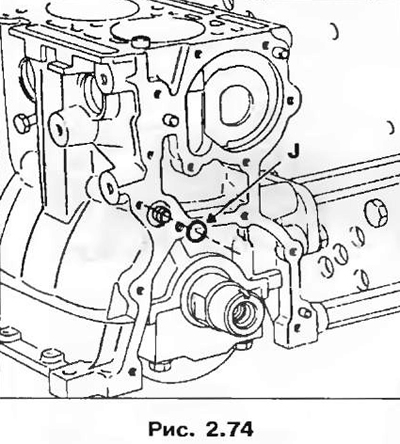
6. Remove the crankshaft oil seal using tool Mot. 1374. Using the nut 1, enter the body of the tool inside the stuffing box and, turning the screw 2, press it out.
7. Remove:
- oil receiver with gasket;
- oil pump.
Attention! The oil pump is beyond repair.
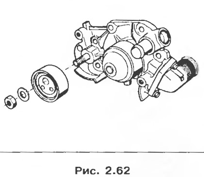
Remove:
- tension roller of the timing mechanism drive and coolant pump.
8. Remove:
- connecting rod caps and liners;
- pistons with connecting rods;
- crankshaft main bearing caps and their liners;
- crankshaft;
- main bearing shells located in the cylinder block.
Disassembly and assembly of the group «connecting rod-piston»
1. Pressing out the piston pins
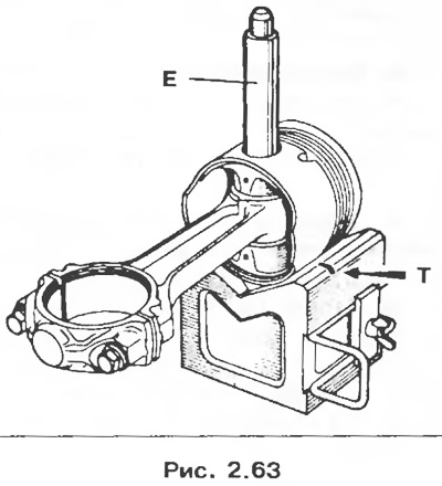
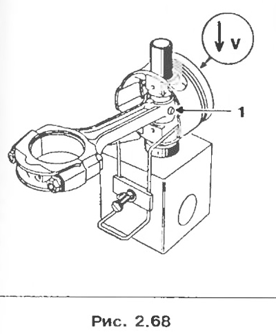
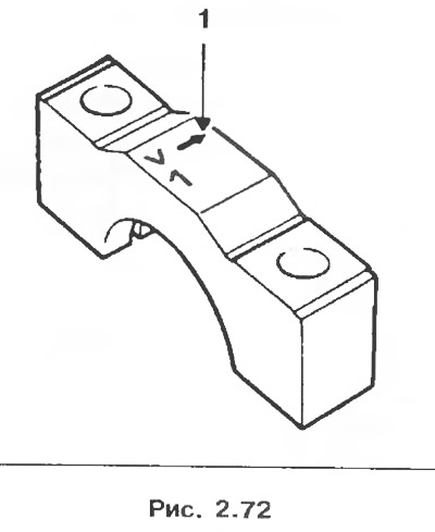
Place the piston in the V-groove so that the piston pin aligns with the hole in the bearing (two T marks on the support indicate the center of the hole, which makes it easier to align). Press out the pin with the tool E.
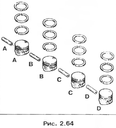
2. Group preparation «piston-pin»
Details of supplied groups «piston-pin» mutually matched. Label each group of packaging parts from A to D in order to maintain a match. Remove the anti-corrosion coating from the parts, but in no case scrape the parts.
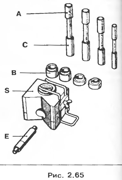
3. Installation of piston pins
The piston pins are pressed into the upper heads of the connecting rods and rotate freely in the piston bosses. The piston pins are installed using tool Mot. 574-21 (supplied as an add-on to tool Mot. 574-22).
A: Mounting mandrels complete with centering sleeves C.
B: Thrust bushings for the piston.
E. Mandrel for pressing fingers.
S: Piston support.
4. Preparing the connecting rods
Check visually:
- condition of connecting rods (twisting and misalignment of the axes of the heads);
- fit of connecting rod caps to connecting rod rods (if necessary, remove burrs with a sanding stone).
Use a 1500W hotplate to heat the cranks. Place the upper ends of the connecting rods on the heating plate.
Make sure that the connecting rod heads fit snugly against the surface of the plate.
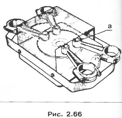
To control the temperature, put a piece of tin solder with a melting point of about 250°C on each upper head of the connecting rod at point a. Heat the top ends of the connecting rods until the solder melts.
5. Preparing the piston pins
Make sure the piston pins slide freely in the bosses of the new pistons.
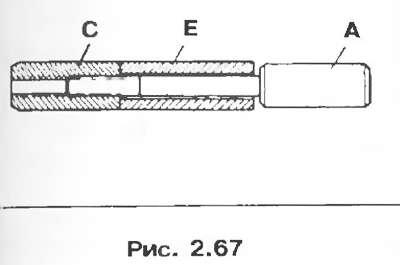
To install the piston pins, use the C17 centering sleeve and the A17 mounting mandrel.
Slide the piston pin E onto the mounting mandrel A, then screw the centering sleeve C onto the mounting mandrel until it stops, and then unscrew it a quarter of a turn.
6. Group assembly «connecting rod-piston»
Note. An arrow is stamped on the piston head, which should point towards the flywheel after assembly. The installation direction of the connecting rod is indicated by projection 1, which must be on the dipstick side.
Install the B17 bushing on the support, put the piston on it together with the pin, securing the piston with the spring stopper of the support (the arrow must be pointing up). Lubricate the centering sleeve and piston pin with engine oil. Insert the piston pin into the piston bores to check and make sure it moves freely, center the piston if necessary.
Once the solder reaches its melting point (turning into a drop), do the following:
- remove a drop of solder from the connecting rod head;
- insert the mandrel centering sleeve into the piston;
- insert the connecting rod into the piston;
- quickly advance the piston pin until the centering sleeve stops one hole in the piston support.
8. Make sure that the pin remains recessed in relation to the outer surface of the piston at any position of the connecting rod in the piston.
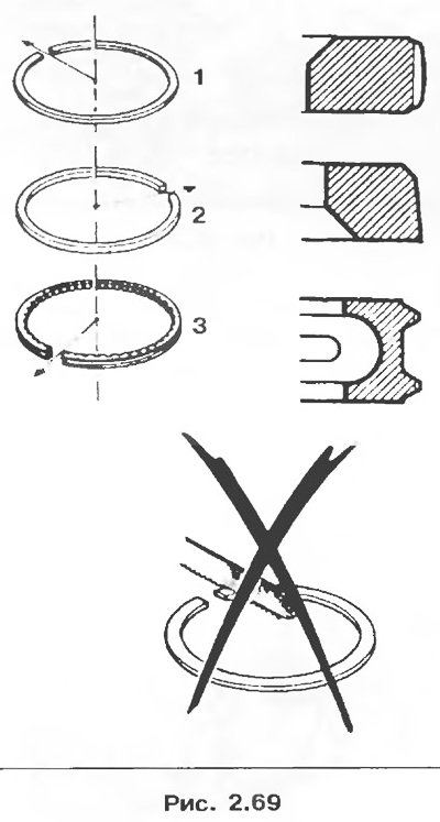
7. Installation of piston rings
The piston rings must move freely in the piston grooves. Be sure to follow the piston ring installation sequence. Lubricate the rings with engine oil and separate their locks (pic. 2.69).
Assembly
1. Install bearing shells. All connecting rod bearings are the same. The crankshaft main bearing shells have lubrication holes on both the cylinder head side and the bearing cap side. The insert of the middle bearing is persistent and determines the axial clearance of the crankshaft.
2. Install the crankshaft.
3. Lubricate the main and connecting rod journals of the crankshaft with engine oil.
4. Replace the bearing caps (pre-lubricate the threads and surfaces under the bolt heads) and tighten the bolts with a torque of 20 Nm, after which they are tightened by an angle of 80°.
Make sure that: the crankshaft rotates freely, the crankshaft axial clearance must be between 0.06 and 0.235 mm.
5. Clear the block of cylinders.
6. Install the pistons with connecting rods in the cylinders of the block using a crimp collar.
7. Install the connecting rod bearing caps so that arrow 1 faces the flywheel.
8. Tighten the connecting rod cap bolts to a torque of 14 Nm, then tighten them by 39°.
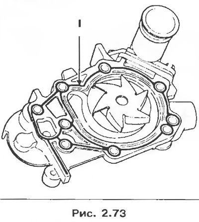
Apply bead 1 of Rhodorseal 5661 to the mating surface of the coolant pump and reinstall the pump.
9. Install a new discharge o-ring with each reassembly.
Attention! The oil pump is driven by two cams located on the crankshaft.
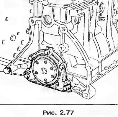
10. Apply bead 5 of Rhodorseal 5661 all around the oil pump mating surface.
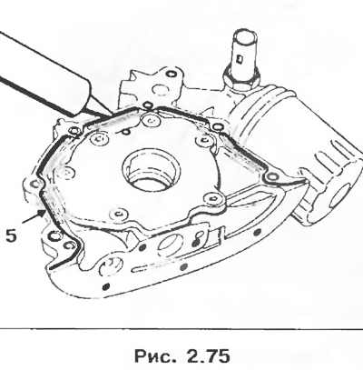
11. Install the oil pump on the cylinder block and tighten the mounting bolts to a torque of 9 Nm.
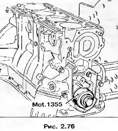
12. Install a new oil seal on the crankshaft, taking care not to damage it when passing through the neck on which the timing gear is installed. Press in the oil seal using tool Mot. 1355.
13. Apply a bead of Rhodorseal 5661 all around the mating surface on the flywheel side.
14. Tighten the cap screws to 9 Nm.
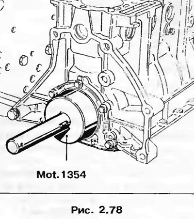
15. Install the crankshaft oil seal using tool Mot. 1354.
16. Install the oil receiver after replacing its sealing ring.
17. Clean the mating surfaces of the cylinder block and oil pan.
18. Install the oil pan, tighten the mounting bolts with a torque of 10 Nm.
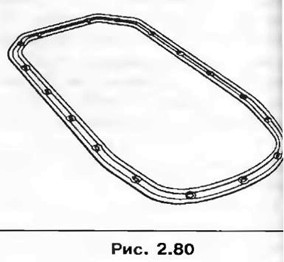
Note. The tightness of the oil pan is ensured only by installing a special gasket (the gasket must face the cylinder block).
19. Installation is carried out in the reverse order.