
Pistons and connecting rods
Removing pistons with connecting rods
Attention:
It is strictly forbidden to apply any pressure to the engine oil pan. Damage to the sump can also cause various damage to the engine itself due to:
- blocking the oil intake;
- increasing the engine oil level above the maximum mark, which can cause the engine to run wild.
1. Remove the power unit assembly from the vehicle.
2. Disconnect the manual transmission from the engine.
3. Remove attachment drive belts.
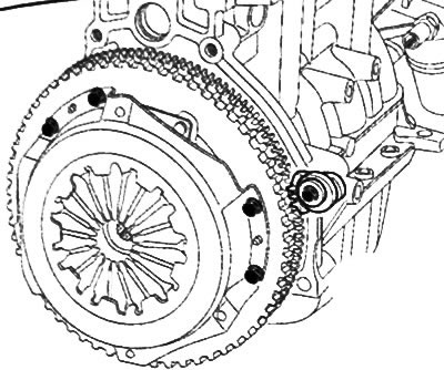
4. Install the flywheel fixing tool (Mot. 582-01) to the cylinder block.
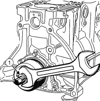
5. Remove the crankshaft pulley.
6. Remove the clutch discs.
7. Remove the flywheel with lock (Mot. 582-01) from the engine.
8. Place the engine on the assembly stand.
9. Drain the engine oil and coolant from the engine.
10. Remove the timing belt (see relevant section of this chapter).
11. Remove the generator.
12. Remove the air conditioning compressor (see relevant section of this chapter).
13. Remove the power steering pump (see relevant section of this chapter).
14. Remove the multifunction support from the engine.
15. Remove ignition coils.
16. Remove intake manifold.
17. Remove the cylinder head.
18. Remove the crankshaft seal from the timing drive side:
Attention: You must be prepared for the fact that fluid may leak from the engine. Protect surrounding components.
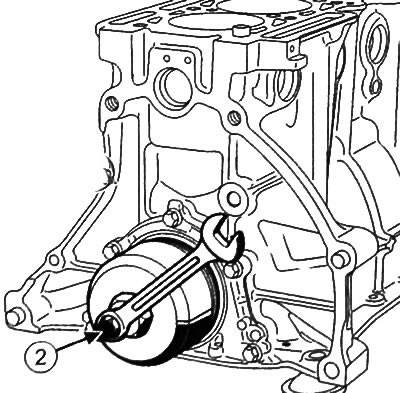
Install the oil pump seal remover (Mot. 1374) to remove the crankshaft oil seal from the timing drive side.
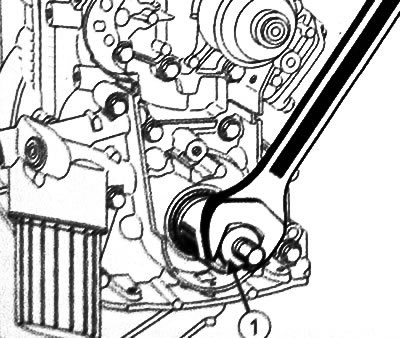
Tighten the nut (1) puller (Mot. 1374).
Tightening the bolt (2) puller (Mot. 1374), remove the crankshaft oil seal from the timing drive side.
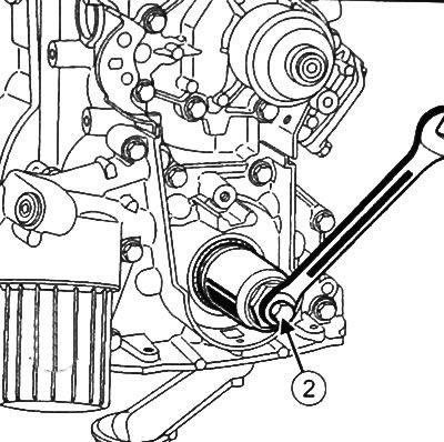
19. Remove the crankshaft oil seal from the gearbox side:
- Place a gland extractor with a stem diameter of 60-70 mm (Mot. 1578) on the flywheel side of the engine.
- Tighten the nut (1).
- Tightening the bolt (2) puller (Mot. 1578), remove the crankshaft oil seal from the gearbox side.
20. Remove the engine oil pan (see chapter "Lubrication system").
21. Remove the oil pump from the engine (see chapter "Lubrication system").
22. Mark with a marker the location of the connecting rods and connecting rod caps in accordance with the cylinder numbers (cylinder 1 flywheel side)
Caution: Do not mark connecting rods and connecting rod caps with punches or engravings, as this may cause cracks. Use only marker.
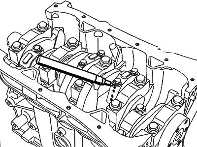
23. Remove connecting rod bolts.
Note: When performing work, use work gloves.
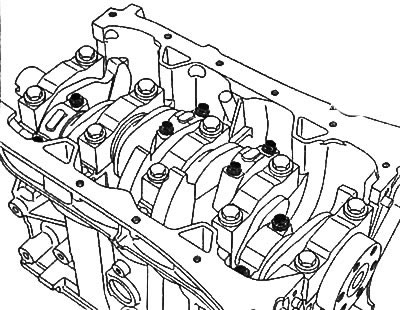
24. Remove the connecting rod caps and remove the connecting rod bearings, marking their position relative to the caps.
25. To take pistons with rods in gathering from a head of the block of cylinders.
26. Remove the upper connecting rod bearings, marking them with a marker relative to the connecting rods.
Disassembly of pistons with connecting rods
Note:
- Piston rings should only be removed when parts need to be replaced or to check the connecting rods or pistons.
- Be careful not to damage the piston when removing the piston rings. Do not expand piston rings too wide as they may burst.
- If reused, mark piston rings against pistons.
1. Using a special tool, remove the piston rings from the piston.
2. Place the piston on the base (1) piston pin replacement kit (Mot. 574-22).
3. With the help of a press and a beard (2) remove the piston pin from the piston by aligning the piston pin with the hole in the base.
4. Disassemble all other pistons with connecting rods in the same way.
Assembly and installation of pistons with connecting rods
Caution: Be sure to replace the connecting rod bolts with new ones.
Note: Do not strike or distort the contact surfaces of the connecting rod cap and connecting rod to prevent damage.
Attention: When performing work, use goggles with side protection.
1. Clean pistons and connecting rods with cleaning agent.
2. Dry pistons and connecting rods with compressed air.
Note:
- The connecting rod bearings do not have any mounting tabs or grooves.
- Use the special tool to install the connecting rod bearings (Mot. 1492) and a set of adapters (Mot. 1492-04).
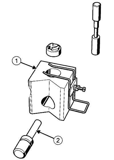
3. Using a vise, remove the pin (3) from the tool for installing bearing shells (Mot. 1492).
4. Replace pin (3) pin (4) from a set of adapters for installing bearing shells (Mot. 1492-04).
5. Move the bearing shell support (5) from a set of adapters for installing bearing shells (Mot. 1492-04) in a groove (6) bearing insert fittings (Mot. 1492).
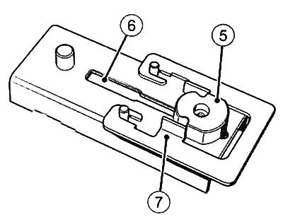
6. Place a frame (7) from a set of adapters for installing bearing shells (Mot. 1492-04) on the base.
7. Place the connecting rod on the tool base.
8. Make sure the bottom (8) the upper head of the connecting rod rests on the centering pin.
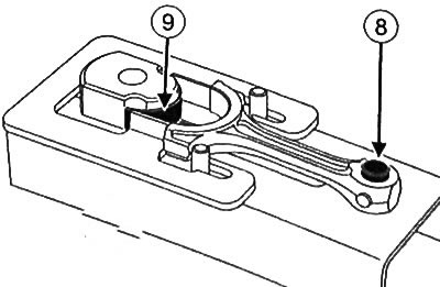
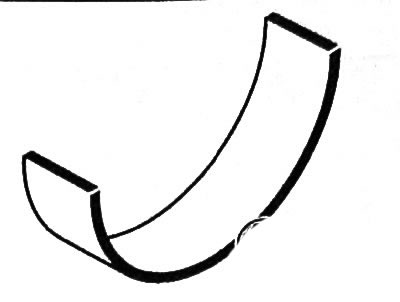
9. Place the bearing shell (9) on a support.
10. Push the bearing shell support (in the direction of the arrow), to fully insert the bushing into the connecting rod.
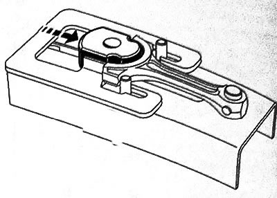
11. Remove the bearing shell support and repeat the operation for the remaining connecting rods.
12. Install a jumper on the fixture (10) and connecting rod cover.
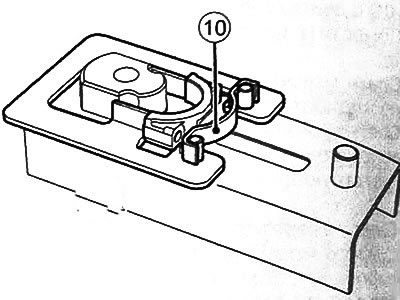
13. Push Frame (in the direction of the arrow), so that the connecting rod cover rests on the jumper.
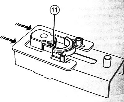
14. Place the bearing shell (11) on the fixture base.
15. Push the bearing shell support (in the direction of the arrow), to fully insert the bushing into the connecting rod cap.
Note:
- If the pistons are replaced with new ones, it is necessary to check their compliance with the size group of the engine cylinder bores (see below).
- If pistons are reused. install them according to the marks made during removal.
16. Visually check the condition of the connecting rods (bending and twisting).
17. Clean the contact surfaces between the connecting rod and the connecting rod cap.
Note: The piston pin has an interference fit in the connecting rod and a loose fit in the piston.
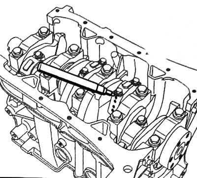
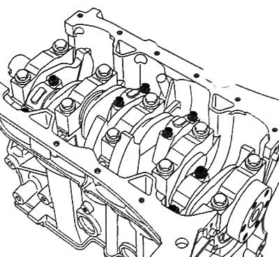
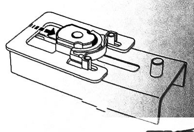
18. Place the connecting rod tops on the hotplate, making sure that the top end bushings are in full contact with the surface of the stove.
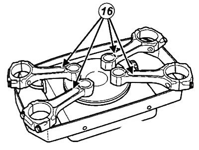
Note: To avoid overheating, place a piece of solder on each upper end of the connecting rods (16), whose melting point is approximately 250°.
19. Heat the upper ends of the connecting rods until the pieces of solder melt.
20.Check that the piston pins fit freely into the bores of the new pistons.
Note: Use dowel pin A19 (17) and centering tool C19 (18) from piston pin replacement kit (Mot. 574-22).
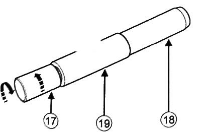
21. Insert piston pin (19) on the dowel pin (17).
22. Screw in the centering device (18) all the way.
23, Loosen the dowel pin (17) those turn around.
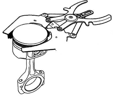
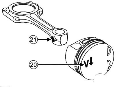
24. Place the piston with the arrow on the bottom (20) down, and the connecting rod so that the ledge (21) was directed towards the oil dipstick on the cylinder block (or referring to the following figure).
25. Place ring B19 on the base of the setting tool.
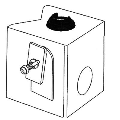
26.Fix the piston with a retainer (22).
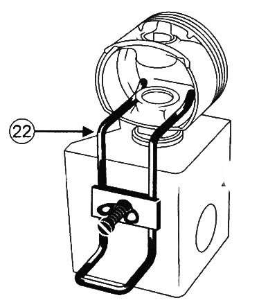
27. Make sure that the hole for the piston pin matches the ring B19 (the arrow on the piston crown must point downwards).
28. Lubricate the centering device and piston pin with engine oil.
29. Insert the piston pin into the assembly to make sure it enters freely. If not, reposition the piston.
Checklist: The following operation must be performed as quickly as possible to avoid early cooling of the connecting rod.
Caution: Wear gloves to avoid burns.
30. After sufficient heating of the connecting rods (pieces of solder on them should melt), remove the solder from the connecting rod and insert the guide into the connecting rod, and then insert the connecting rod into the piston on the special tool.
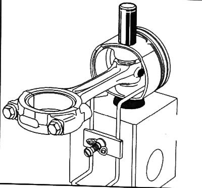
31. Quickly press in the piston pin so that the guide from the connecting rod reaches the edge of the tool base.
32. Make sure that the piston pin does not protrude beyond the edges of the piston skirt.
33. Clean the grooves in the piston.
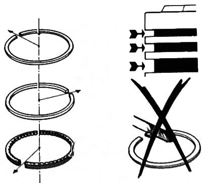
34. Install the piston rings in their places, paying attention to the fact that the mark "TOR" on the surface of the piston rings was directed upwards.
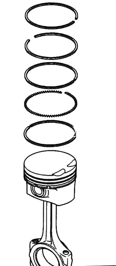
35. Arrange the locks of the piston rings at different angles to each other, as shown in the figure.
36.Lubricate the piston with engine oil and compress the piston rings with a tool for installing pistons in the engine cylinders.
37. Lubricate the engine cylinders and crankshaft connecting rod journals with engine oil.
38.Install the piston and connecting rod assembly and check that the piston number matches the engine cylinder number (Cylinder #1 is on the flywheel side), and also that all the installation marks on the piston crown are located correctly (The arrow on the bottom must point towards the flywheel).
39. Install the rest of the pistons in the same way.
40.Install the connecting rod ends on the crankshaft journals.
41. Install the connecting rod caps according to the previously marked marks on the connecting rods.
42. Tighten the connecting rod bolts to 14 Nm, and then tighten another 39°±6°.
43.Install the oil pump and engine sump (see chapter "Lubrication system").
Note: Be sure to replace the crankshaft oil seals with new ones after each removal.
Caution: To ensure proper sealing, crankshaft oil seals must be clean, dry and free of grease (avoid any fingerprints).
44.Install the crankshaft oil seal on the gearbox side:
- Use a cleaning agent to degrease the contact surfaces on the crankshaft and the oil seal housing in the cylinder block.
Note: This type of oil seal is very brittle, so a special tool must be used to install it (Mot. 1625).
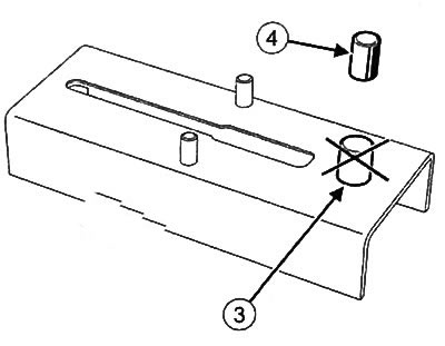
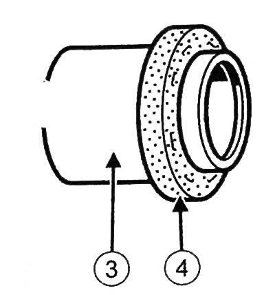
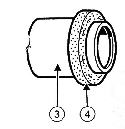
Attention: To prevent leakage after installation, when installing the gland, only touch the protective element (3). It is strictly forbidden to touch the gland itself (4).
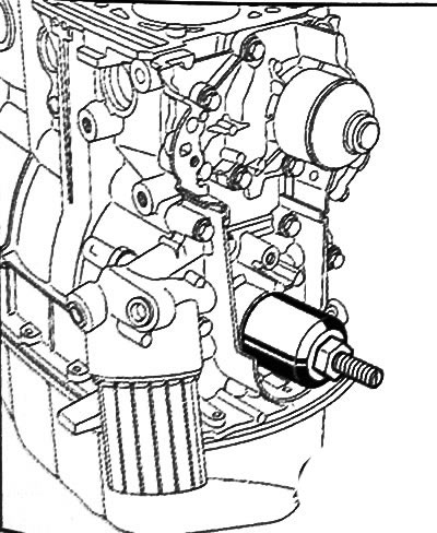
- Install the seal installer (Mot. 1625) on the crankshaft, fixing it with bolts (5).
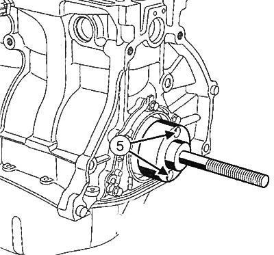
- Install the protective element with the gland in place on the fixture (Mot. 1625), being careful not to touch the seal.
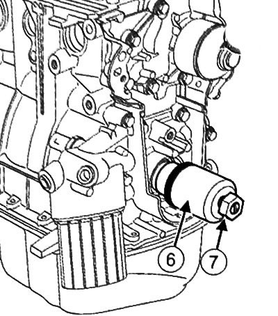
- Install cover (6) and a nut (7) as it shown on the picture.
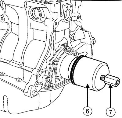
- Screw in the nut until the cover rests on the cylinder block.
- Loosen the nut and remove the cover, protective element and tool base.
45. Install the crankshaft oil seal on the timing gear drive side:
- Use a cleaning agent to degrease the contact surfaces on the crankshaft and the oil seal housing in the cylinder block.
Note: This type of oil seal is very brittle, so a special tool must be used to install it (Mot. 1626).
Attention: To prevent leakage after installation, when installing the gland, only touch the protective element (3). It is strictly forbidden to touch the gland itself (4).
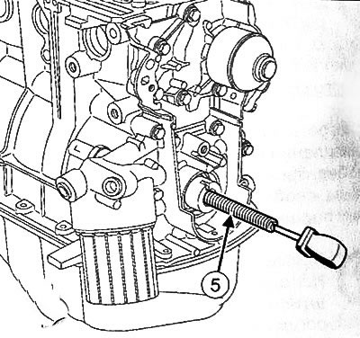
- Insert threaded rod (5) stuffing box press tools (Mot. 1626) into the crankshaft.
- Install the protective element with the gland on the threaded rod of the device, taking care not to touch the gland.
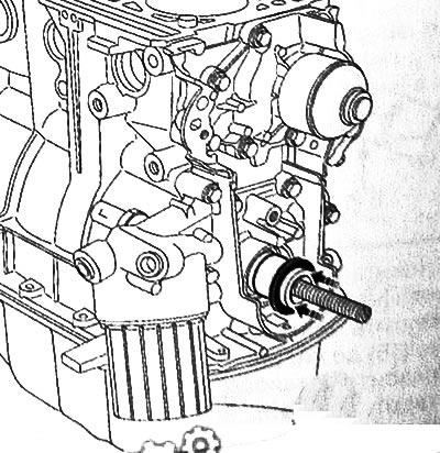
- Install cover (6) with nut (7) tools for installing the crankshaft oil seal on the timing drive side (Mot. 1626).
- Screw in the nut until the tool cover (Mot. 1626) stuck in the spacer.
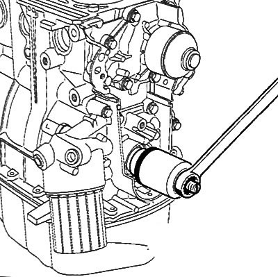
- Tighten tool nut (Mot. 1626) so that the tool cover rests on the cylinder block panel.
- Unscrew the nut and remove the cover, the protective element and the threaded rod of the tool for installing the crankshaft oil seal on the timing gear end (Mot. 1626).
46. Install the cylinder head.
47. Install the intake manifold.
48. Install ignition coils.
49. Install the multifunction support.
50. Install the power steering pump.
51. Install the air conditioning compressor.
52.Install the generator.
53.Install the timing belt.
54.Fill engine oil into the engine.
55.Remove the engine from the assembly stand.
56.Install flywheel.
57. Install flywheel locking tool (Mot. 582-01).
58.Install the clutch discs.
59. Install the crankshaft pulley.
60.Remove the flywheel locking tool from the cylinder block.
61.Install the attachment drive belts.
62.Install the gearbox on the engine.
63. Install the power unit assembly to the vehicle.