
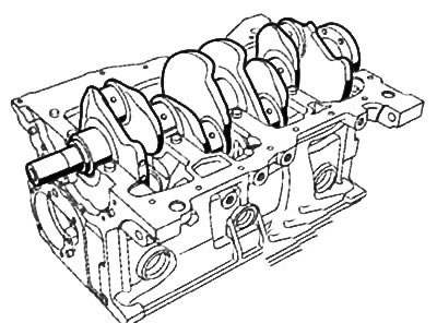
Removing the crankshaft
1. Remove the pistons with connecting rods from the engine (see section above).
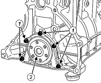
2. Loosen the mounting bolts (1) and remove the crankshaft thrust plate (2).
3. Make sure that the marks made on the crankshaft main bearing caps at the factory are legible (bearing #1 is on the flywheel side).
Caution: Do not mark the crankshaft bearing caps with punches or engravings as this may cause cracking. Use only marker.
4. If necessary, mark the crankshaft main bearing caps with a marker. Also mark the installation direction of the covers.
Note: Be sure to mark the position of each main bearing shell with a marker according to the main bearing numbers.
5. To turn away bolts of fastening of covers of radical bearings of a cranked shaft and to remove covers from the block of cylinders.
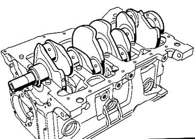
6. To take a cranked shaft from the block of cylinders.
7. To take loose leaves of radical bearings and basic half rings.
Installing the crankshaft
Attention:
- Be sure to replace the main bearing cap bolts with new ones after each removal.
- The sealing surfaces must be clean, dry and free from grease to ensure the required tightness (avoid any fingerprints).
Note: Do not strike or warp the contact surfaces of the main bearing caps to prevent damage.
1. Clean the crankshaft, main bearing caps, main bearing shell housings in the cylinder block and the contact surfaces of the cylinder block with the main bearing caps with a cleaning agent.
Attention: For the following operation, use goggles with protective sidewalls.
2. Dry all parts with compressed air.
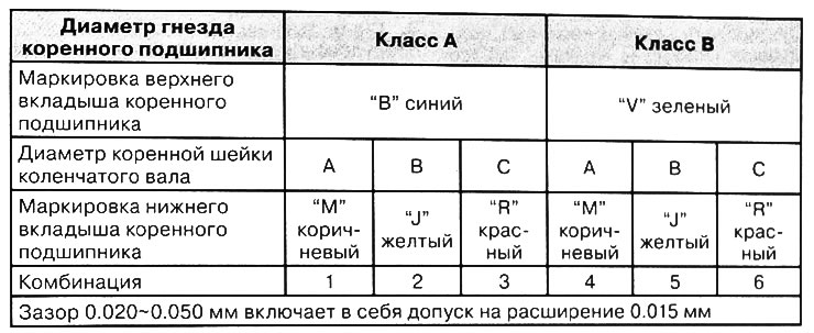
Note: When replacing the crankshaft or crankshaft main bearing shells, be sure to determine the thickness class of each bushing to ensure the required clearance in the crankshaft main bearings (see below). Crankshaft main bearing clearance mismatch can cause engine damage.
3. Select the main bearing shells of the appropriate size groups (see below).
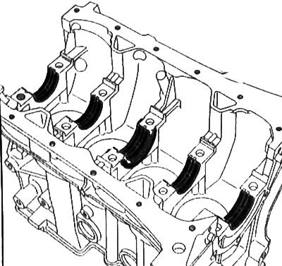
4. Install the grooved main bearing shells in the cylinder block seats:
- Install the main bearing shell installer (Mot. 1493-02) to the cylinder block.
- Insert the main bearing shell with groove into the tool (Mot. 1493-02).
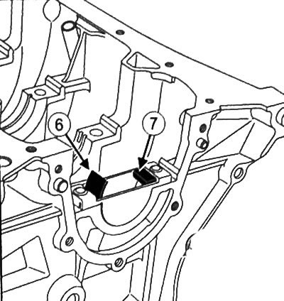
- Press in the main bearing (6) so that it comes into contact with the bar (7) fixtures.
Note: The thrust washers are built into the #3 main bearing shell.
5. Insert the main bearing shells without grooves into the main bearing caps:
- Install the main bearing shell installer (Mot. 1493-02) on the main bearing cap.
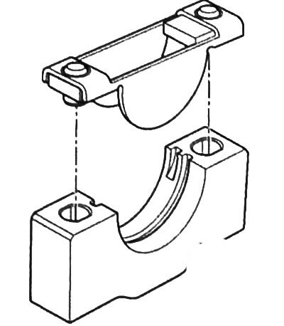
- Insert the main bearing shell with groove into the tool (Mot. 1493-02).
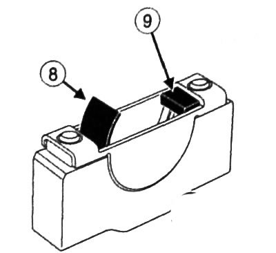
- Press in the main bearing (8) so that it comes into contact with the bar (9) fixtures.
6. Apply oil to the crankshaft main bearing shells (only on surfaces in contact with the crankshaft).
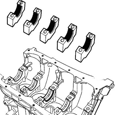
7. Install the crankshaft in the cylinder block.
8. Install the main bearing caps by placing the #1 cap on the flywheel side.
Note: The arrows on the main bearing caps must point towards the flywheel.
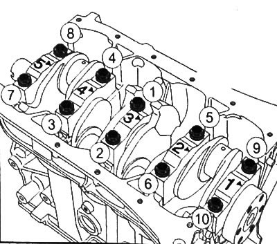
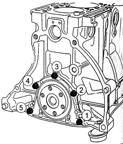
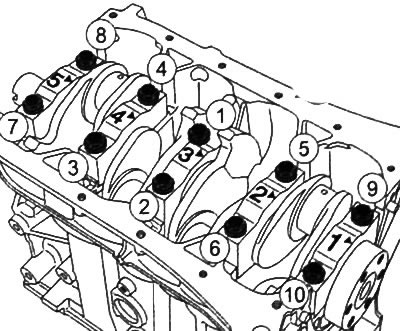
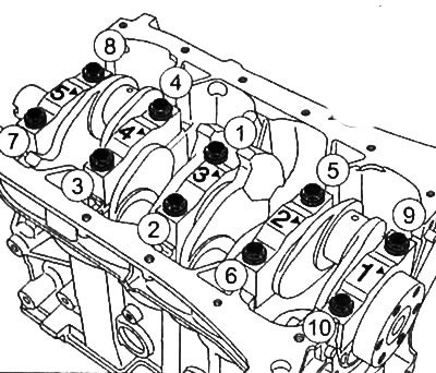
9. Tighten the bolts of the main bearing caps in the sequence shown in the figure to a torque of 20 Nm, and then tighten each bolt another 76°± 6°.
10.Check that the crankshaft rotates easily and without jamming.
eleven. Install pistons with connecting rods (see relevant section in this chapter).
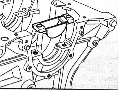
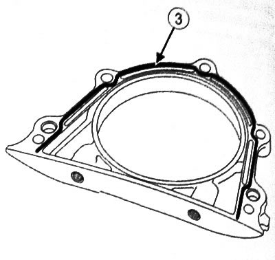
12.Install the crankshaft thrust plate:
- Apply a bead of MASTIXO sealant (3) 1.3 mm thick on the contact surfaces of the stop plate as shown in the figure.
Attention:
- Excess applied sealant may be squeezed out when tightening threaded connections. Sealant entering the coolant may cause damage to some components (engine, radiator, etc.).
- Install the crankshaft thrust plate on the cylinder block and tighten the mounting bolts in the sequence shown in the figure to a torque of 9 Nm.
Note: Further assembly is described in the section "Installing pistons with connecting rods".
Checking the crankshaft and selecting the main bearing shells
1. Remove the crankshaft from the engine.
2. Clean crankshaft with cleaning agent and dry with compressed air.
3. Check that the crankshaft is free from scratches, impact marks, or abnormal wear. If any defects are found, replace the crankshaft with a new one.
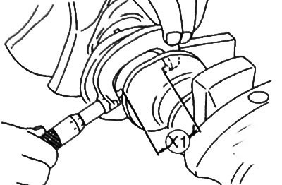
4. Using a micrometer, measure the diameter of the main journals of the crankshaft (X1). This value should be 44±0.01mm.
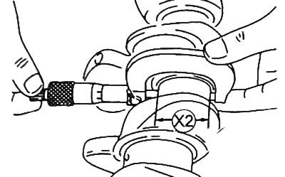
5. Using a micrometer, measure the diameter of the connecting rod journals of the crankshaft (X2). This value should be 39.985-40 mm.
Note:
- The main bearing shells do not have any locating lugs or grooves.
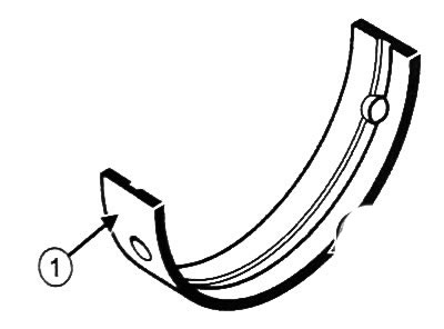
- Bearing shells are marked with letters according to color (B = blue, J = yellow, M = brown, R = red, V = green).
- For installing main bearing shells (1) use a special tool (Mot. 1493-02).
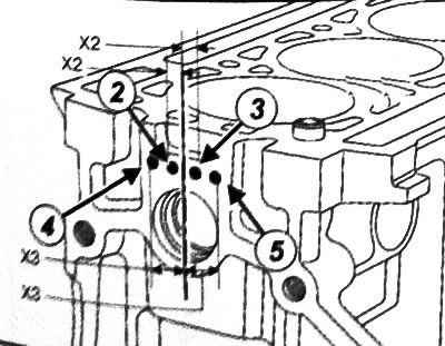
Note: Holes (2) And (3) indicate, respectively, classes A and B of the upper shells of the main bearings and are located at a distance (X2) - 5 mm from the vertical axis of the crankshaft. In addition to single holes (A or B), corresponding to the class of upper main bearing shells, holes may be present (4) or (5), used for industrial purposes and located at a distance (HZ) - 12 mm from the vertical axis of the crankshaft.
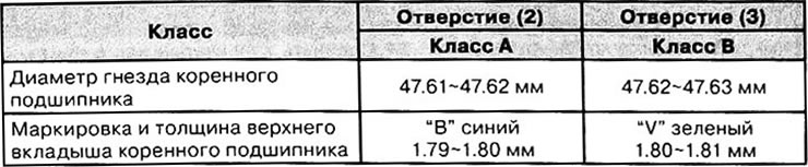
Upper main bearing shells
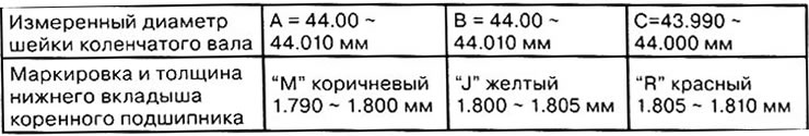
Lower shells of main bearings
Combinations
6. Install the crankshaft main bearing shells using a special tool (Mot. 1493-02).
7. Remove oil from the crankshaft main journals and from the main bearing shells in the cylinder block.
8. Install the crankshaft without lubrication.
Note: Do not rotate the crankshaft while checking.
9. Place a piece of round gauge parallel to the axis of the crankshaft main journal.
10. Loosely install the main bearing caps by placing the #1 cap on the flywheel side.
Note: The arrows on the main bearing caps must point towards the flywheel.
11. Tighten the bolts of the main bearing caps in the sequence shown in the figure to a torque of 20 Nm, and then tighten each bolt by another 76°± 6°.
12. To remove covers of radical bearings of a cranked shaft.
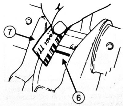
13. Measure the width of the most flattened part of the round probe (6) according to the scale on the packaging of the round dipstick (7). The gap value should be 0.020-0.045 mm.
14. Remove the remnants of a round probe from the crankshaft main journals and main bearing caps.
15. Apply oil to the crankshaft main bearing shells (only on surfaces in contact with the crankshaft).
16. Install thrust washers and crankshaft.
17. Install the main bearing caps by placing cap #1 on the flywheel side.
Note: The arrows on the main bearing caps must point towards the flywheel.
18. Tighten the main bearing cap bolts in the sequence shown in the figure to a torque of 20 Nm, and then tighten each bolt another 76°± 6°.
19. Check that the crankshaft rotates easily and without jamming.
20.Install the dial gauge with support as shown in the figure.
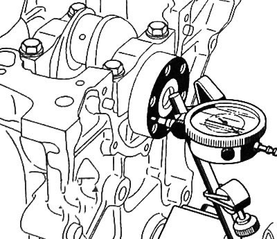
21. Place a dial indicator probe on the flywheel mounting surface on the crankshaft.
22. Support the crankshaft against the thrust half ring by pushing it towards the dial indicator.
23.Reset the dial gauge.
24. Move the crankshaft in the opposite direction (from dial indicator).
25.Read the value of the crankshaft end play from the dial gauge. The axial play of the crankshaft must not exceed 0.275 mm