
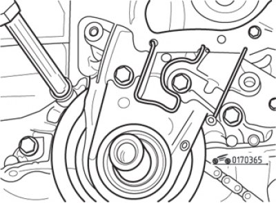
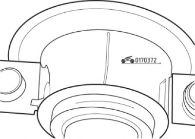
Pic. 3.65. Removal of the case of a forward epiploon of a cranked shaft
Loosen the bolts securing the crankshaft front oil seal housing and remove it (pic. 3.65). Remove both crankshaft seals.
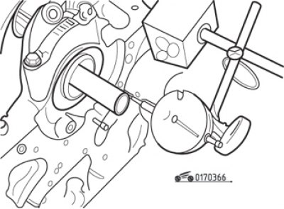
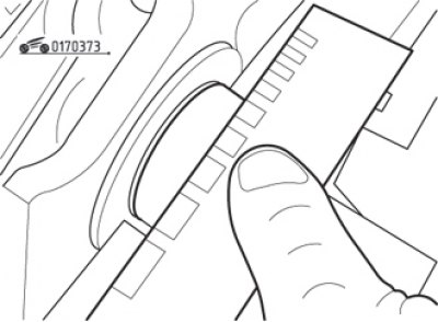
Pic. 3.66. Measurement of crankshaft end play
Before removing the crankshaft, check its axial clearance. To perform the measurement, a dial indicator is used, the leg of which rests against the toe of the crankshaft (pic. 3.66). Move the shaft to the stop along its axis, set the indicator arrow to zero and move the shaft to the stop in the opposite direction. Record the indicator reading and compare it with that given in Table. 3.3.
If you don't have a dial indicator, use a set of flat feeler gauges. To do this, shift the crankshaft towards the flywheel, and then use feeler gauges to measure the gap between the side surface of the second connecting rod journal and the semi-ring in the central bearing of the crankshaft.
Withdrawal order:
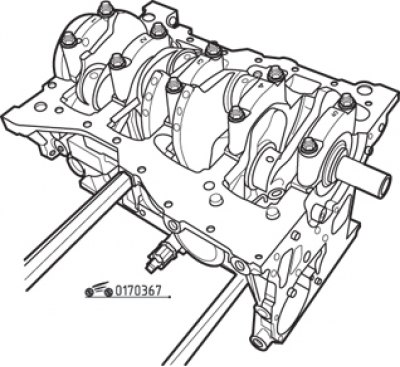
Pic. 3.67. Marking of covers of main bearings of a cranked shaft
- make sure there are legible markings on the main bearing caps. The number indicates the position of the bearing in the crankcase, counted from the flywheel side (pic. 3.67);
- Carefully loosen the main bearing cap bolts half a turn per pass until they can be removed by hand. Turn out bolts, then separate covers from a crankcase. Remove the lower main bearing shells and store for later inspection;
- remove the crankshaft from the engine block, being careful not to drop the upper main bearing shells, which may be on the crankshaft. Then remove the remaining upper main bearing shells from the journals on the cylinder block and store for later inspection;
- remove the thrust washers on either side of the third main journal.
Inspection
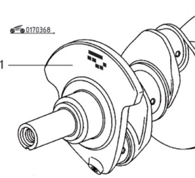
Pic. 3.68. Main bearing journal diameter marking on crankshaft counterweight (1)
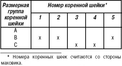
Wash the crankshaft with kerosene or other suitable solvent. Dry it with compressed air if possible. Clean the oil holes with a wire and blow with compressed air. On the counterweight on the side of the toe of the shaft there is a marking by which you can determine the diameters of the journals of the main bearings (pic. 3.68). The decoding of the marking is given in table. 3.5.
Table 3.5. Deciphering the markings on the crankshaft
Inspect the main and connecting rod journals for wear, cracks, scuffing, electrochemical corrosion. If such signs are found, grind the crankshaft at a specialized service station.
In this case, it will be necessary to install new liners of the appropriate repair size.
Using a micrometer, measure the diameter of each of the bearing journals in several places. Compare the measurement results with the values given in tab. 3.3. If the journals are worn more than 0.025 mm, the crankshaft should be reground to the repair size.
If measurements taken at 90°intervals give different diameters, this means that the main journal is oval. The discrepancy between the diameters measured at different points along the length of the main neck indicates the presence of a taper of the neck. As in the previous case, grinding is necessary, followed by the installation of repair size liners.
Check the surfaces mating with the crankshaft seals. If they have significant scuffing or damage, consult a specialist for advice on the suitability for further use of the crankshaft.
Using a V-prism and a dial gauge, measure the radial runout of the crankshaft. The maximum allowable radial runout is no more than 0.05 mm. If the runout exceeds this value, consult a specialist for advice on the suitability of the crankshaft for further use.
Inspection of the liners of main and connecting rod bearings
Even if you plan to use new liners, which is highly recommended, do not throw away the old ones immediately after removal, as a thorough inspection of them can provide valuable information about the condition of the engine and the causes of malfunctions. Signs of major defects can be seen in Fig. 3.69.
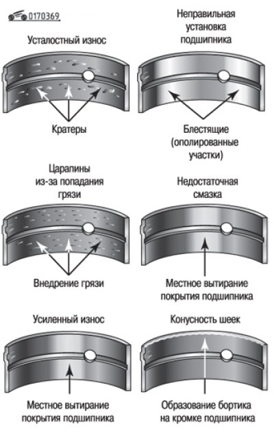
Pic. 3.69. The main types of damage to bearing shells
Damage caused by the ingress of foreign particles into the engine looks like longitudinal marks on the main and connecting rod bearings. Abrasive particles sometimes remain in engine parts after reconditioning, especially if the parts have not been thoroughly cleaned using the proper methods. Often these are metal particles that appeared after machining and as a result of engine wear during operation. They can get into the oil, and from it, passing through the filters, into the bearings. The best way to prevent such damage is to keep all engine parts immaculately clean, both during assembly and during engine operation.
Carry out, as indicated in the operating instructions, regular replacement of engine oil and filter.
Damage due to lack of lubrication looks like the liner material has been rubbed, chipped, or squeezed out of the steel base. The reason for this is overheating, which causes the oil to dilute (often the liners get a bluish tint), overload (which leads to the extrusion of oil from the bearing coating and, as a result, chipping and cracking). Lack of lubrication can also be caused by excessive clearances in the oil pump or constant operation of the engine at high speeds, clogged lubrication channels (use of inappropriate oil, its untimely replacement).
Electrochemical corrosion of bearing shells can be caused by constant travel over short distances. In this case, the heat generated during a short trip by the engine is insufficient to remove water vapor and corrosive gases. These substances accumulate in engine oil, forming acid and sludge. As oil flows to the engine bearings, the acid attacks the bearing material and causes corrosion.
Incorrect installation of the liner during assembly also leads to its failure. Bushings that are too tight leave insufficient running clearances, resulting in a lack of lubrication. Dirt or foreign particles that have fallen on the back of the liner cause it to bulge and wear out. Therefore, do not touch the inner working surface of the earbuds with your fingers when assembling - you may scratch the surface, which requires careful handling, or leave dirt particles on it.
As already mentioned, with any disassembly of the engine, it is recommended to replace the liners; otherwise, you get only apparent savings.
Installation
Installation order:
- place the cylinder block on a clean horizontal surface with the crankcase up;
- Wipe dry with a lint-free cloth the backs of the earbuds and their beds in the block and covers;
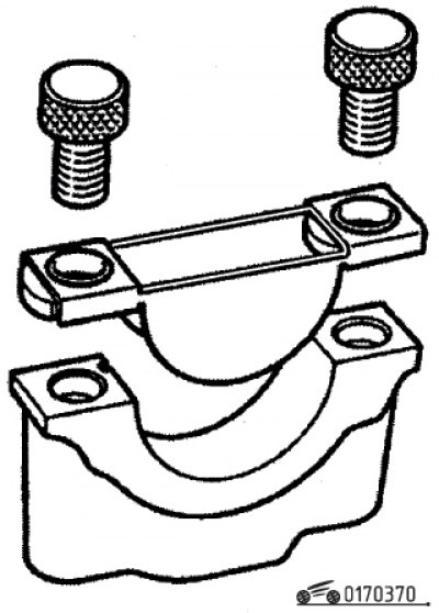
Pic. 3.70. Renault tool Mot. 1493-01 for pressing bed liners
- place the liners in their respective beds using the Renault tool Mot. 1493-01 (pic. 3.70);
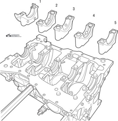
Pic. 3.71. Installing the crankshaft main bearing shells
- Install grooved liners in the cylinder block bed. In the covers of supports 1, 3, 5 (pic. 3.71) install liners without grooves, and in covers 2 and 4 - with grooves;
- install thrust half rings on both sides of the 3rd support of the cylinder block. The lubrication grooves must face outward;
- check the clearances in the crankshaft bearings before final installation using a special Plastigage kit. The set is a plastic calibrated round bar. If a piece of bar is clamped between two parts, then by its deformation, using the attached scale, you can determine the gap between these parts;
- Carefully place the crankshaft into the cylinder block. Do not use grease on either the shaft or the bushings;
Pic. 3.72. A piece of Plastigage plastic bar laid on the crankshaft main journal
- cut five pieces of plastic rod and lay them on each main shaft journal, as shown in fig. 3.72;
- carefully, without moving the bars, place the corresponding covers with the liners installed in them on the supports;
- starting from the 3rd support, tighten the cover bolts in the prescribed order to the specified torque; do not rotate the crankshaft while tightening the covers;
- unscrew the bolts securing the covers and carefully remove them without moving the flattened bar from the surface of the shaft neck;
Pic. 3.73. Determining the clearance in the bearing according to the Plastigage scale
- use the scale supplied with the kit to determine the clearances in each bearing (pic. 3.73). Compare the results obtained with those given in table. 3.3;
- if the gaps are larger than allowed, the bearings may not be the correct size (or too worn, if the measurement was set to the previous). Before deciding on a crankshaft, make sure that no oil or dirt has entered the gap where the measuring rod was installed. If the flattened bar is wider at one end than at the other, it is likely that the neck has tapered wear. Consult with an engine rebuilder whether to rebuild worn parts or replace them with new ones;
- at the end of the operation, scrape off with a soft scraper all the remnants of the bar from the surfaces of the bearings and the shaft, being careful not to damage the bearings;
- carefully remove the crankshaft from the cylinder block;
- Wipe the bearing shells and crankshaft journals again with a rag. Make sure that there are no dirt, dust, Plastigage residues in the lubrication holes and on the surfaces of the crankshaft, as this dirt will be in the bearings after the first start of the engine;
- lightly grease the thrust half rings on the side of the 3rd support and install them outward with the lubrication grooves;
- lubricate the bearing shells with clean engine oil, then carefully install the crankshaft on the bearing journals;
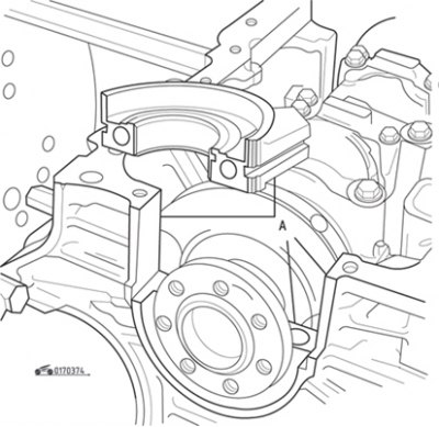
Pic. 3.74. Clean contact surfaces before applying sealant (A) covers of the 1st support
- make sure the bushings are properly installed in the bearing caps, lubricate them with clean engine oil and install on the block in the required order with the correct orientation, while applying a thin layer of PHODORSEAL 5661 sealant to the entire contact surface of the 1st bearing cap (pic. 3.74 and 3.75);
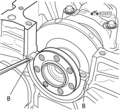
Pic. 3.75. Applying sealant to the underside (IN) cylinder block
- install the bolts on the support covers and tighten them diagonally from the middle outwards in a certain order with the set torque;
- check the rotation of the crankshaft - it should be easy, without jamming. If force is required to rotate, find out the cause before proceeding with further assembly;
- check the axial clearance of the crankshaft as described above;
- install the crankshaft oil seal on the flywheel side;
- Install the lower rear timing belt cover.