



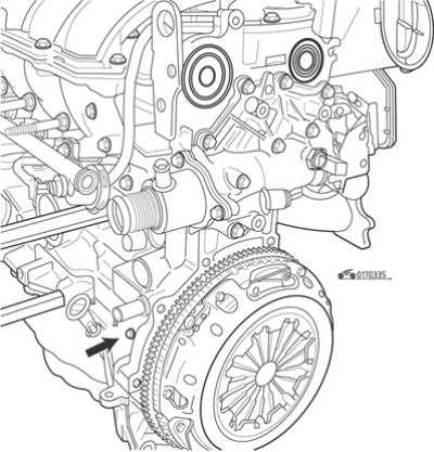
Fig. 3.35. Hole plug (arrow) for screwing the retainer into the cylinder block
To perform the above operations, it is necessary to install the piston of the first cylinder (from the flywheel side) to the top dead center (TDC) position at the end of the compression stroke. In order to determine this position, Renault uses a special locking device that is screwed into a hole in the front part of the cylinder block closed with a threaded plug (Fig. 3.35).
Work order:
- remove the air filter housing and resonator box from the left side of the engine;
- use a screwdriver to remove the plastic plugs on the left side of the cylinder head that cover the ends of the camshafts;
- remove the right front wheel and plastic mudguard to access the crankshaft pulley;
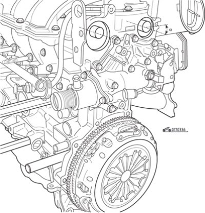
Fig. 3.36. Position of the grooves on the ends of the camshafts: a=30°
- using a head with a ratchet, turn the crankshaft by the pulley bolt in the direction of engine rotation until the grooves on the ends of the camshafts take the position shown in Fig. 3.36, and tilt it at an angle of approximately 30° to the horizontal;
- unscrew the plug from the cylinder block (see fig. 3.35) and screw the locking pin in completely. If there is no locking pin, TDC can be determined using a dial indicator screwed into the spark plug hole of the first cylinder;
- screw in the TDC locking pin, then slowly, without jerking, turn the crankshaft by the pulley bolt one turn clockwise (when viewed from the timing drive side) until the shaft rests against the retainer.
This position of the crankshaft corresponds to the piston of the first cylinder being at TDC at the end of the compression stroke.
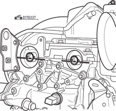
Fig. 3.37. Location of grooves on the ends of the camshafts when installing the piston of the first cylinder at the end of the TDC of the compression stroke
Make sure that the position of the camshaft grooves corresponds to the position shown in Fig. 3.37.
To fix the position of the camshafts, Renault uses a special metal plate that is installed in the grooves of the shafts and attached to the cylinder head. It is easy to make such a tool yourself.
Removal procedure:
- disconnect the negative battery cable;
- apply the parking brake, jack up the front of the car and place safety supports under the body;
- remove the accessory drive belts as described in subsection "Checking the condition of auxiliary drive belts";
- set the crankshaft to the TDC position of the piston of the first cylinder at the end of the compression stroke, as described above;
- lift the power unit by placing a piece of wood under the jack head;
- remove the upper right engine pendulum mount bracket and travel limiter (see fig. 3.09);
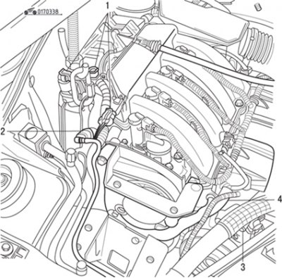
Fig. 3.38. Removing the electrical connectors (1), hose (2), mounting tab (3), and mounting bolt (4) of the wiring harness bracket from the engine
- disconnect (Fig. 3.38) electrical connectors 1, disconnect hose 2, remove fastening tab 3 and wiring harness bracket fastening bolt 4;
- disconnect the wiring harness from the upper timing cover and move it to the side;
- disconnect the fuel lines from the lower timing cover;
- secure the flywheel with a wide screwdriver and unscrew the crankshaft pulley mounting bolt;
Warning! The bolt is tightened with a very high torque. Be careful.
- remove the crankshaft pulley;
Article reprinted from the website: RenaultBook.ru
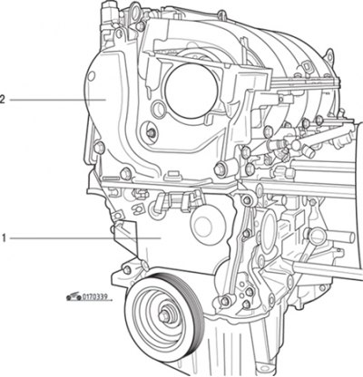
Fig. 3.39. Timing belt covers: 1 - lower; 2 - top
- remove the timing belt covers by unscrewing their mounting bolts (Fig. 3.39);
- loosen the timing belt by unscrewing the tension roller axle mounting nut;
Attention! The toothed pulley of the crankshaft is attached without a key; make sure it does not fall when removing the timing belt. The keyway on the nose of the crankshaft should be at the 12 o'clock position if the piston of the first cylinder is at TDC of the compression stroke.
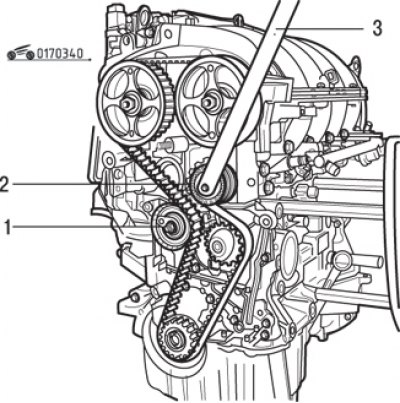
Figure 3.40. Timing belt of the gas distribution mechanism: 1 – tension roller; 2 – idler roller; 3 – Mot. 1368 tool for removing the idler pulley
- remove the idler pulley using the tool (Fig. 3.40);
- remove the timing belt;
- inspect the removed belt. If there is oiling, cracks, wear of teeth, delamination and similar defects, the belt must be replaced. The cause of oiling should be identified and eliminated;
Note: Renault recommends replacing the timing belt each time it is removed, and also replacing the tensioner and idler pulleys.
- thoroughly clean and degrease the crankshaft nose, the bearing surface of the crankshaft pulley, and the seating surface of the crankshaft sprocket to prevent them from slipping against each other, which could lead to engine failure.
Installation procedure:
- install the camshafts as shown in Fig. 3.37;
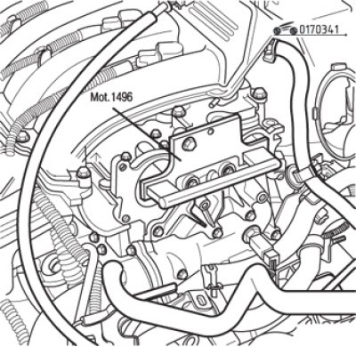
Fig. 3.41. Fixing camshafts using a Renault device
- fix the position of the camshafts using the Renault Mot. 1496 device (Fig. 3.41) or using a self-made device;
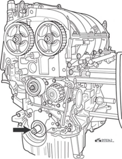
Fig. 3.42. The keyway on the nose of the crankshaft (arrow) should be in the "12 o'clock" position
- make sure that the crankshaft is securely locked with the top dead centre lock Mot. 1489 and that the crankshaft keyway is at the 12 o'clock position (Fig. 3.42);
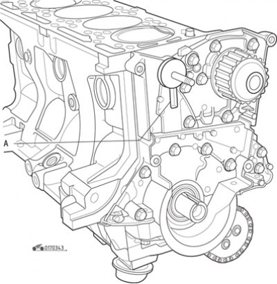
Fig. 3.43. Groove (A) into which the tension roller protrusion should enter
- when installing the tension roller, make sure that the roller protrusion fits correctly into groove A (Fig. 3.43);
- install the belt on the crankshaft sprocket, then on the water pump pulley, idler pulley, around the camshaft sprockets and tensioner. Make sure the belt is installed in accordance with the arrows indicating its direction;
- tighten the idler pulley mounting bolt to the specified torque;
- install the pulley on the crankshaft nose, do not tighten it with a bolt - the gap between the bolt and the pulley should be 2-3 mm;
Caution! The crankshaft pulley mounting bolt is suitable for reuse if the length of the bolt to the head does not exceed 49.1 mm (otherwise replace the bolt). Do not lubricate a new bolt with engine oil. On the contrary, a reused bolt must be lubricated with engine oil.
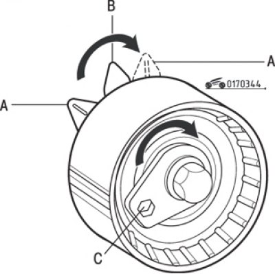
Fig. 3.44. Tension roller: A - movable pointer; B - fixed pointer; A' – position of the movable indicator after adjusting the belt tension; C – hole for hexagon
- tension the belt by turning the tension roller clockwise so that the movable pointer A (Fig. 3.44) takes position A' at a distance of 7–8 mm from the fixed pointer B. Turn the roller using a hex key inserted into hole C. Pre-tighten the tension roller to a torque of 7 N·m;
- tighten the crankshaft pulley mounting bolt to 20 Nm, then turn it further by 135°±15°, while the crankshaft must be locked with the TDC lock;
- remove the camshaft locking tool and TDC locking tool;
- turn the crankshaft two turns clockwise (when viewed from the timing drive side), screw the locking pin into the cylinder block until the end of the rotation and slowly, without jerking, move the crankshaft until it stops in the locking pin;
- unscrew the retainer from the hole in the cylinder block;
- loosen the tension roller axle mounting nut no more than one turn, holding the roller from turning with a hex key;
- align the movable pointer A with the fixed pointer B and finally tighten the nut to a torque of 27 N·m;
- turn the crankshaft again and make sure the timing marks match;
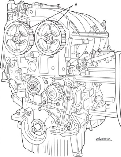
Fig. 3.45. Installing the camshaft toothed pulleys: A – Renault emblem
Note. If it is necessary to remove the camshaft toothed pulleys, when installing them, position them so that the Renault emblem on the pulley spokes is at the top in the 12 o'clock position (Fig. 3.45). When tightening the toothed pulley fastening nuts, use a device that prevents them from turning.
- install the upper and then the lower belt covers, tightening the bolts securely;
- screw the TDC hole plug into the cylinder block;
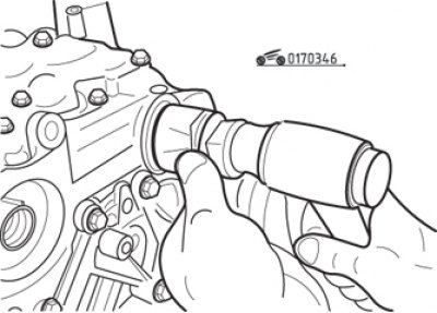
Fig. 3.46. Installing plugs for the ends of camshafts using a mandrel
- install new plastic plugs for the ends of the camshafts using suitable mandrels (Fig. 3.46);
- perform the remaining operations in the reverse order of removal.