
| Tightening torques | |
| Bolt of fastening of a bypass roller of a timing belt | 50 Nm |
| Bolt of fastening of a new pulley of a cranked shaft | 40 Nm + 145°±15° |
| Nut of fastening of a tension roller of a timing belt | 27 Nm |
| Bolts of fastening of the lower cover of the timing drive | 12 Nm |
| Nuts of fastening of all gear pulleys of a camshaft | 30 Nm + 84°±4° |
| Hole plug for TDC lock | 20 Nm |
| Bolts of fastening of the top cover of the timing drive | 46 Nm |
| Nuts of fastening of the top cover of the timing drive | 46 Nm |
| Flywheel side lifting eye bolts | 10 Nm |
Removing
Place the car on a two post lift.
Disconnect the battery.
Remove:
- intake air duct,
- intake silencer,
- right front wheel
- accessory drive belt,
- crankshaft pulley,
- the right support of the pendulum suspension of the engine.
Remove:
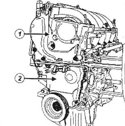
- upper timing cover bolts (1),
- upper timing cover,
- lower timing cover bolts (2),
- lower timing cover.
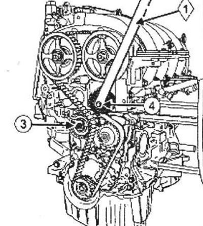
Loosen the nut (3) fastening the axis of the tension roller of the timing drive.
Note: Do not drop the crankshaft sprocket when removing the timing belt.
Remove:
- timing belt tensioner bolt (4) using a device (1),
- timing belt pulley,
- timing belt,
- nut of fastening of an axis of a tension roller,
- timing belt tensioner,
- crankshaft toothed pulley.
Installation. 1st way
Parts that must be replaced:
- timing belt,
- Timing belt tensioner,
- crankshaft pulley bolt,
- Inlet camshaft plug,
- Timing belt pulley,
- Exhaust camshaft plug.
The first method is used to replace any elements located in the front of the timing drive with a crankshaft toothed pulley without a key, while it is not necessary to loosen the fastening parts of one or two camshaft toothed pulleys.
1 - Setting the valve timing
Attention! Be sure to degrease:
- crankshaft end (from the timing drive),
- boring and bearing surfaces of the timing gear pulley,
- bearing surfaces of the crankshaft pulley,
- camshaft ends (on the timing side),
- holes and bearing surfaces of the toothed pulleys of the camshafts.
This is necessary to avoid displacement of the timing drive.
Such a relative displacement leads to engine failure.
Position the camshaft grooves horizontally and offset downwards from the camshaft axes, turning the camshafts with a tool if necessary.
Install:
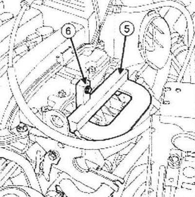
- adaptation (5) at the ends of the camshafts,
- lifting eye bolt (6), to pin.
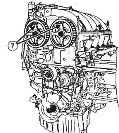
Arrange the RENAULT logos (7) on the spokes of the camshaft pulleys vertically upwards.
Install the new timing belt tensioner pulley by inserting its tab into the groove (8).
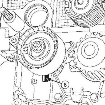
Wrap, without tightening, a nut of fastening of an axis of a tension roller.
Install:
- toothed pulley (9) crankshaft,
- new belt,
- new timing belt pulley (10).
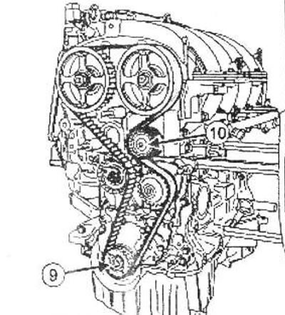
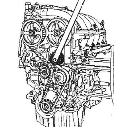
Torque tighten the timing belt idler pulley bolt (50 Nm) using the fixture.
Using a 6 mm Allen wrench, align the movable pointer (11) notched (12), by turning the eccentric (13) clockwise.
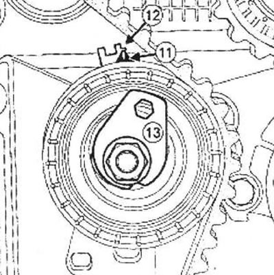
Torque tighten the timing belt tensioner nut (7 Nm).
Install the tool on the cylinder block.
Note: There are two types of timing case bottom covers:
- without hatch for installation of gas distribution phases,
- with a hatch for installing valve timing.
A - The lower cover of the timing drive with a hatch for setting the valve timing
Install the lower timing cover (14).
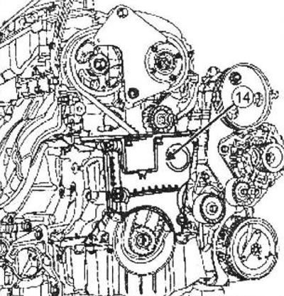
Torque tighten the bolts securing the lower timing cover (12 Nm).
B - continuation of the installation procedure, regardless of the type of lower timing cover
Install a new idle pulley.
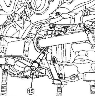
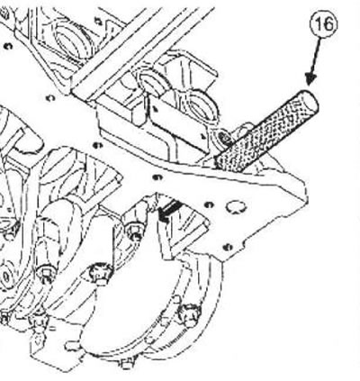
Use a screwdriver (15), to make sure the flywheel does not turn (clockwise when viewed from the timing end), otherwise turn the engine crankshaft until it stops against the tool (16) with a screwdriver; the crankshaft groove should be at the top.
 |  |
Tighten to the required torque and tighten the bolt of the new crankshaft pulley to the required angle (40 Nm + 145°±15°) (while the crankshaft must touch the fixture).
C - The lower cover of the timing drive with a hatch for setting the valve timing
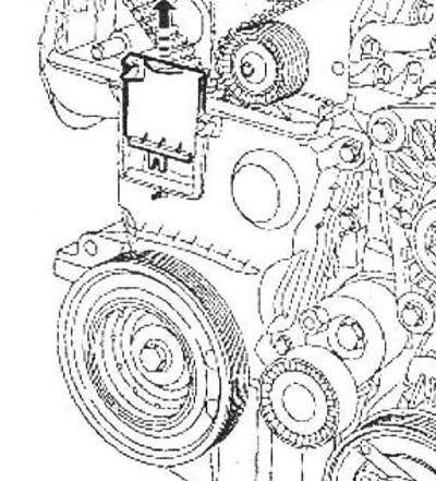
Remove the manhole cover for installing the valve timing on the lower timing cover.
D - continuation of the installation procedure, regardless of the type of lower timing cover
Remove:
- fixture bolt,
- device for setting the valve timing,
- from the cylinder block.
3 - Checking the timing belt tension
Rotate the crankshaft two turns clockwise (when viewed from the timing side) and until the previously applied marks are combined (on the phase regulator pulley), screw the tool into the hole in the cylinder block.
Slowly and without jerking, bring the crankshaft to the stop in the fixture.
Remove the tool from the cylinder block.
Make sure the movable pointer (17) located opposite the recess (18), if it's not:
- unscrew the nut securing the tension roller no more than one turn, while holding the movable pointer with a 6 mm hex wrench,
- smoothly move the movable pointer (17) before alignment with the notch (18), by turning the eccentric (19) clockwise.
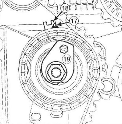
Torque tighten the timing belt tensioner nut (27 Nm).
4 - Checking the installation of the valve timing
Before checking the installation of the valve timing, make sure that the pointer and the notch of the tension roller are in the correct position.
Screw the tool into the cylinder block.
Slowly and without jerking, bring the crankshaft to the stop in the fixture.
Install (without making an effort) camshaft locking tool (the grooves at the ends of the camshafts must be in a horizontal position and be shifted down from the axes of the shafts).
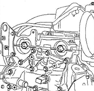
Note: If the camshaft locking tool does not snap into place, you need to reset the valve timing and adjust the timing belt tension.
Remove:
- device for setting the valve timing,
- from the cylinder block.
A - The lower cover of the timing drive with a hatch for setting the valve timing
Install the manhole cover on the lower timing cover, making sure that the pin (20) enters the recess (21).
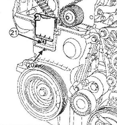
B - The lower cover of the timing drive without a hatch for setting the valve timing
Install the lower timing cover.
Torque tighten the bolts securing the lower timing cover (12 Nm).
Installation 2nd method
Parts that must be replaced:
- timing belt,
- Timing belt tensioner,
- Timing belt pulley,
- crankshaft pulley,
- Nut of fastening of a gear pulley of a camshaft,
- crankshaft pulley bolt,
- Inlet camshaft plug,
- Exhaust valve housing plug.
The second procedure is used to replace any items in the front of the timing chain with or without keyed crankshaft sprocket that require loosening one or both camshaft sprockets.
Install the tool on the camshaft pulleys using the tool.
Loosen the nuts (22) all toothed camshaft pulleys.
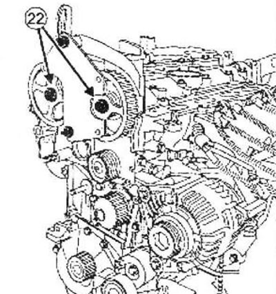
Remove:
- fixture from the cylinder block,
- all nuts of fastening of gear pulleys of camshafts,
- camshaft pulleys.
1 - Setting the valve timing
Attention! Be sure to degrease:
- crankshaft end (from the timing drive),
- boring and bearing surfaces of the timing gear pulley,
- bearing surfaces of the crankshaft pulley,
- camshaft ends (on the timing side),
- holes and bearing surfaces of the toothed pulleys of the camshafts.
This is necessary to avoid displacement of the timing drive.
Such a relative displacement leads to engine failure.
Position the camshaft grooves horizontally and offset downwards from the camshaft axes, turning the camshafts with a tool if necessary.
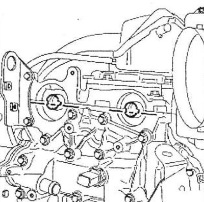 | 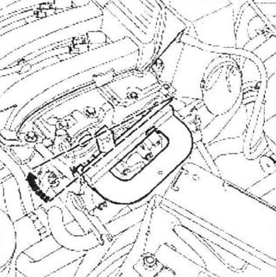 |
Install:
- adaptation (23) at the ends of the camshafts,
- and bolt mb (24), to keep.
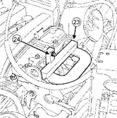
Install:
- crankshaft pulley,
- camshaft pulleys,
- all nuts of fastening of gear pulleys of camshafts.
Install the tool on the cylinder block.
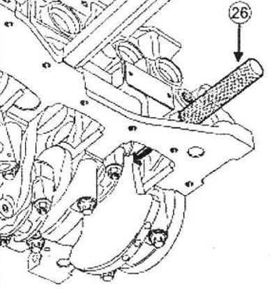
Use a screwdriver (25), to make sure the flywheel does not turn (clockwise as viewed from timing end), otherwise turn the engine crankshaft until it stops against the tool (26) with a screwdriver; the crankshaft groove should be at the top.
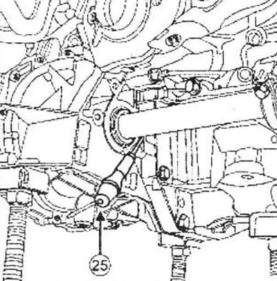
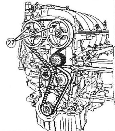
Arrange the RENAULT logos (27) on the spokes of the camshaft pulleys vertically upwards.
 |  |
2 - Installation
Install the new timing belt tensioner pulley by inserting its tab into the groove (28).
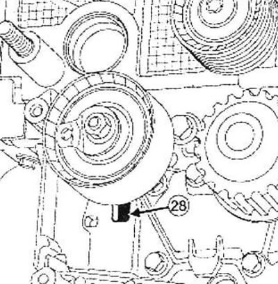
Wrap, without tightening, a nut of fastening of an axis of a tension roller.
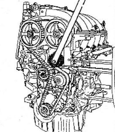
Install a new timing belt, starting with the toothed pulleys of each camshaft (without turning the camshaft pulleys).
Install fixture (29) on the camshaft pulleys (use the top timing cover bolt and nut to install the tool).
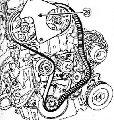
Note:
- Try to properly tension the timing belt between the two camshaft pulleys.
- If the engine is equipped with a crankshaft sprocket with a key, try to properly tension the timing belt between the exhaust camshaft sprocket and the crankshaft sprocket.
Install a new timing belt idler pulley.
Torque tighten the timing belt idler pulley bolt (50 Nm) using the device.
3 - Adjusting the timing belt tension
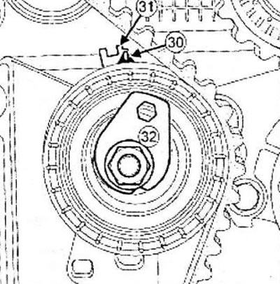
Align the movable pointer with a hex wrench (30) notched (31), by turning the eccentric (32) clockwise.
Torque tighten the timing belt tensioner nut (7 Nm).
Note: There are two types of timing case bottom covers:
- without hatch for installation of gas distribution phases,
- with a hatch for installing valve timing.
A - The lower cover of the timing drive with a hatch for setting the valve timing
Install the lower timing cover (33).
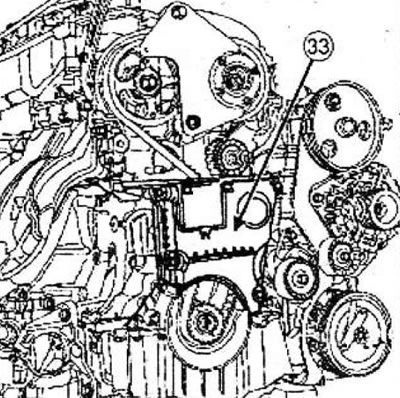
Torque tighten the bolts securing the lower timing cover (12 Nm).
B - Continuation of the installation procedure, regardless of the type of lower timing cover
Install a new idle pulley.
Tighten to the required torque and tighten to the specified angles:
- new crankshaft pulley bolt (40 Nm + 145°±15°),
- nuts of fastening of all gear pulleys of a camshaft (30 Nm + 84°±4°).
C - The lower cover of the timing drive with a hatch for setting the valve timing
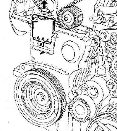
Remove the manhole cover for installing the valve timing on the lower timing cover.
D - continuation of the installation procedure, regardless of the type of lower timing cover
Remove:
- fixture bolt,
- fixture,
- fixture from the cylinder block,
- diagnostic device.
4 - Checking the timing belt tension
Rotate the crankshaft two turns clockwise (when viewed from the timing side) and until the previously applied marks are combined (on the phase regulator pulley), screw the tool into the hole in the cylinder block.
Slowly and without jerking, bring the crankshaft to the stop in the fixture.
Remove the tool from the cylinder block.
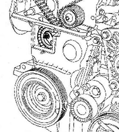 | 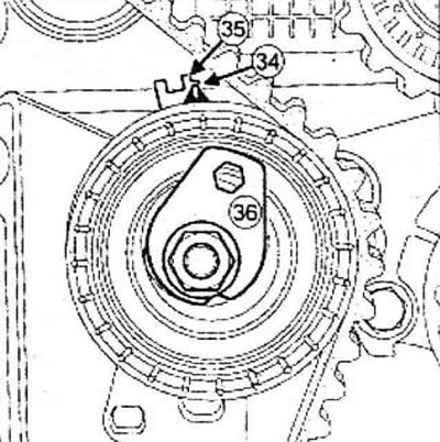 |
Make sure the movable pointer (34) located opposite the recess (35), if it's not:
- loosen the tensioner nut by no more than one turn while holding the movable pointer with a hex wrench,
- smoothly move the movable pointer (34) before alignment with the notch (35), by turning the eccentric (36) clockwise.
Torque tighten the timing belt tensioner nut (27 Nm).
5 - Checking the installation of the valve timing
Before checking the installation of the valve timing, make sure that the pointer and the notch of the tension roller are in the correct position.
Screw the tool into the cylinder block.
Slowly and without jerking, bring the crankshaft to the stop in the fixture.
Install (without making an effort) (the grooves of the camshafts must be in a horizontal position with a downward shift from the axes of the shafts).
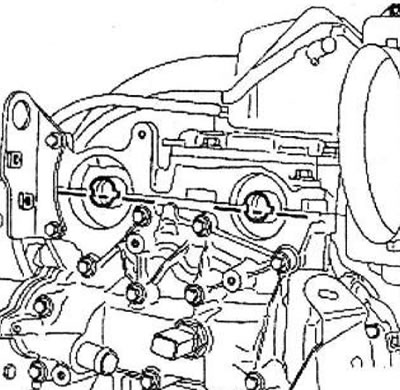
Note: If it fails to install, it is necessary to re-install the valve timing and adjust the timing belt tension.
Remove the valve timing tool from the cylinder block.
A - The lower cover of the timing drive with a hatch for setting the valve timing
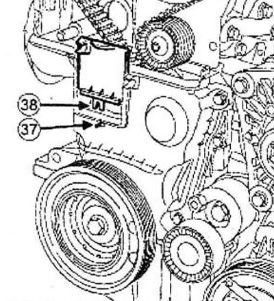
Install the manhole cover on the lower timing cover, making sure that the pin (37) enters the recess (38).
B - The lower cover of the timing drive without a hatch for setting the valve timing
Install the lower timing cover.
Torque tighten the bolts securing the lower timing cover (12 Nm).
Apply a drop of silicone sealant to the threads of the TDC retainer plug.
Torque tighten the hole plug for the TDC retainer (20 Nm).
Remove the top timing cover.
Torque tighten:
- upper timing cover bolts (46 Nm),
- top timing cover nuts (46 Nm).
Install:
- a new inlet camshaft plug using the tool
- a new exhaust camshaft plug using the tool
- flywheel side engine lifting eye.
Torque tighten the lifting eye mounting bolts on the flywheel side (10 Nm).
Install:
- right pendulum suspension support,
- accessory drive belt,
- right front wheel
- intake silencer,
- air intake pipeline.
Connect the battery.