
Removal
When removing the timing belt, the following special tools must be used:
- belt tension checker Mot 1273;
- centering fork of the pendulum suspension travel limiter Mot. 1289-02;
- top dead center lock (TDC) Mot. 1318;
- tension roller deflection lever Mot. 1370;
- adjusting roller tightening wrench Mot. 1368;
- lever for deflecting the eccentric adjusting roller Mot. 1369;
- tension roller lock Mot. 1376;
- ball joint remover T. Av. 476.
Disconnect the cable from the negative terminal of the battery.
Use the charging station to discharge the refrigerant from the air conditioning circuit.
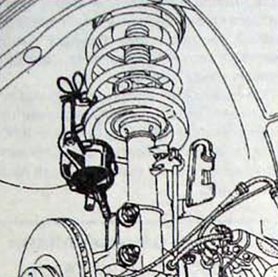
Pic. 3.26. Attaching the brake caliper bracket to the front suspension spring
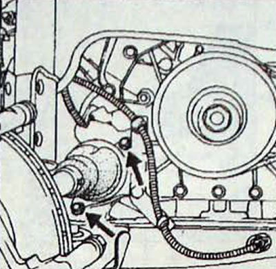
Pic. 3.27. Location of bolts securing the intermediate support of the drive shaft in the support bearing
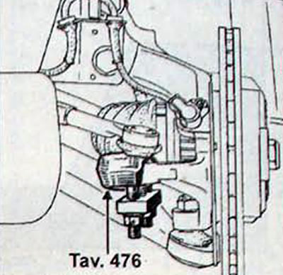
Pic. 3.28. Using the Tav puller. 476 to disconnect the tie rod end from the steering knuckle
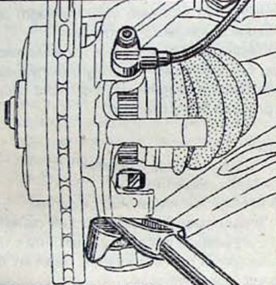
Pic. 3.29. Using an Impact Puller to Press Out the Lower Ball Joint
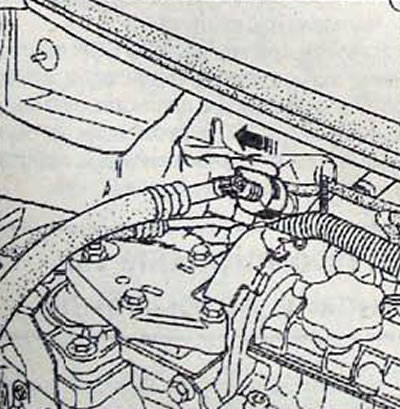
Pic. 3.30. Direction of movement when disconnecting the quick-release connections of the air conditioning hoses
Remove:
- right front wheel;
- protective shields under the engine;
- front right wheel arch protective liner;
- jet thrust;
- the intake pipe of the exhaust system.
On the left side of the car
- Remove the drive shaft by first removing:
- the front right floating brake caliper bracket and to protect the brake hose from damage, secure it to the suspension spring;
- Unscrew the two bolts securing the intermediate support of the drive shaft in the support bearing;
- using the T.Av puller. 476 tie rod end;
- unscrew the bolts of the lower fastening of the shock-absorbing strut;
- wheel speed sensor
- Loosen the lower ball joint end nut as far as possible and use a ball joint impact remover (for example FACOM D98) press the tip out of the steering knuckle.
- Remove the drive shaft - steering knuckle - brake disc assembly. Do not damage the corrugated covers of the drive shafts.
- Support the engine oil pan with a wooden support.
- Remove the 4 bolts and the right suspension bracket and its support.
- Carefully remove the pendulum suspension.
- Using NAUDER tool No. 7240 and 7242, disconnect the quick-release connections of the air conditioning system hoses on the mudguard.
- Remove the fuel fine filter bracket with the booster pump.
- Remove the accessory drive belt.
- Remove the accessory drive belt pulley from the crankshaft.
- Remove the timing belt covers.
Note. When carrying out operations on the gas distribution mechanism drive, it is recommended to raise or lower the engine relative to the vehicle, taking the following as travel restrictions:
- - up: touching the oil filler cap to the front panel;
- down: maximum 70 mm travel.
- Turn the crankshaft until. while the mark is on the crankshaft pulley (C, fig. 3.31) will not be directed downward, and the mark (D) on the camshaft pulley - on the left at an angle of approximately 45° (The inner mark A of the camshaft pulley should be opposite the mark on the cylinder head cover) and label (I) injection pump pulley - opposite the mark on the injection pump casing.
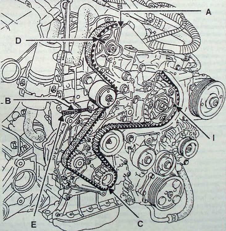
Pic. 3.31. Position of the marks when setting the valve timing: A - internal mark of the camshaft pulley; B - nut; C - crankshaft pulley mark; D-mark of the camshaft pulley; E - adjusting bolt; I - high pressure fuel pump pulley mark
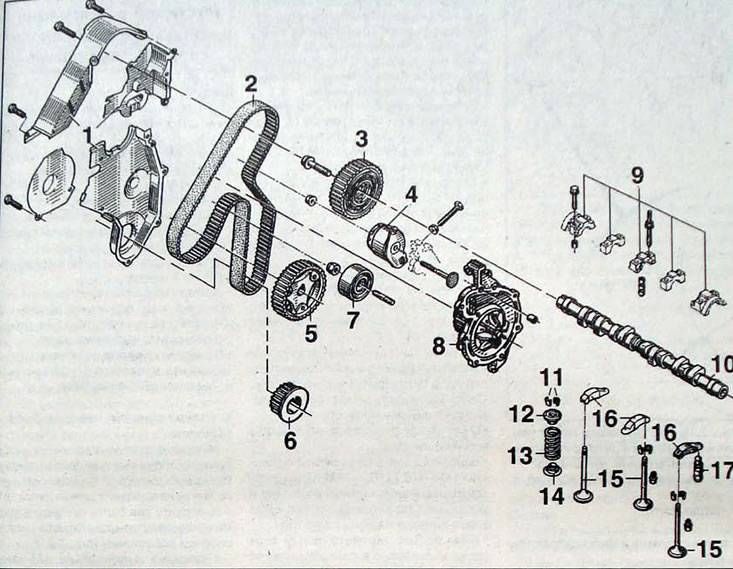
Fig. 3.32. Timing belt drive of the gas distribution mechanism: 1 - timing belt casing; 2 - timing belt; 3 - camshaft pulley; 4 - tensioner roller; 5 - fuel pump pulley; 6 - crankshaft pulley; 7 - tension roller; 8 - water pump driven by a toothed belt; 9 - camshaft bearing caps; 10 - camshaft; 11 - crackers; 12 - upper spring plate; 13 - valve spring; 14 - lower spring plate; 15 - valves; 16 - valve rocker arm; 17 - hydraulic compensator
- With the Mot. 1318 or a rod with a diameter of 7 mm, block the crankshaft. by inserting the tool into the hole closed with a plug and located on the cylinder block between the flywheel and the oil filter.
- Unscrew the nut (IN) and screw (E) and loosen the timing belt.
- Remove the timing belt.
Installing the timing belt and timing
- Visually check the condition of the timing belt and replace it if there are traces of oil or coolant, cracks, missing or worn teeth.
- Make sure that the tensioner roller rotates easily and smoothly, without jamming, otherwise replace it. To replace the roller, lift the engine with a lifting mechanism and completely unscrew the central nut securing the roller.
- Make sure the TDC lock Mot 1318 is in place. Align all valve timing marks.
- Install the timing belt, aligning the marks on the pulleys and the belt.
Note.
- The following procedure for adjusting belt tension must be strictly followed.
- Do not turn the engine crankshaft in the opposite direction to the operating direction.
- Belt tension is adjusted using an adjusting bolt (E, Figure 3.31).
- Rotating the bolt (E. fig. 3.31) tighten the timing belt, while the bracket-mark (N, fig. 3.33) tension roller must align with the stop (F) and, without applying much force, tighten the adjusting screw lock nut.
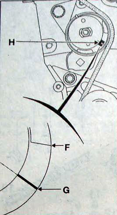
Pic. 3.33. Location of marks when tensioning the timing belt: N - tension roller bracket; F - stop; G - hatch mark
- Remove the TDC lock and turn the crankshaft 3 full turns clockwise until the piston of the 1st cylinder is set to the TDC position. Re-insert the TDC lock
- Unscrew the lock nut of the adjusting bolt, then gradually move the tension roller to the nominal position when the hatch mark (G. fig. 3.33) passes through the center of the bracket-mark (N).
- Tighten the tensioner roller nut to the required torque.
- While holding the adjusting bolt (E, fig. 3.31) from turning, tighten the lock nut (IN).
- Remove the crankshaft locking device and close the hole that opens in the cylinder block with a plug.
- Install the timing belt cover.
- Clean the crankshaft pulley bearing surface.
- Apply 2 drops of LOCTITE AUTOFORM locking agent to the crankshaft pulley bearing surface and install the accessory drive belt pulley onto the crankshaft.
- Be sure to replace the crankshaft pulley bolt with a new one and tighten it to a torque of 25 Nm. then tighten it to an angle of 64±6°.
- Install the accessory drive belt.
- On vehicles with air conditioning, install the upper accessory drive belt guard.
- Install the fuel filter and booster pump bracket, while replacing the copper seals of the pipeline connections
- On vehicles with air conditioning system, use Nauder tool 7240 and 7242 to connect the pipe quick connectors.
- Install the engine suspension bracket and use tool Mot. 1289-02 center the suspension travel stop.
- Remove the jack that supported the engine.
- Install the exhaust pipe.
- Install jet thrust;
- Install the plastic mud guard to protect the engine and the right front wheel.
- Install the right front wheel
- Connect the wire to the negative terminal of the battery
- Lower the car.