
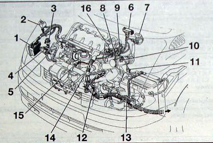
Pic. 3.20. Location of various engine management system components and wiring harnesses in the engine compartment with the G8T 714 engine: 1 - engine control unit; 2 - engine warm-up control unit; 3 - inertial shock sensor; 4 - fuel heater temperature sensor; 5 - electric fuel heater; 6 - acceleration sensor; 7 - EGR solenoid valve; 8 - coolant temperature sensor; 9 - coolant temperature indicator in the instrument cluster; 10 - air temperature sensor; 11 - speed sensor; 12 - speed sensor and crankshaft position; 13 - reverse light switch; 14 - solenoid valve for fast idle speed; 15 - temperature sensor of the air conditioning system; 16 - fuel injector needle lift sensor connector
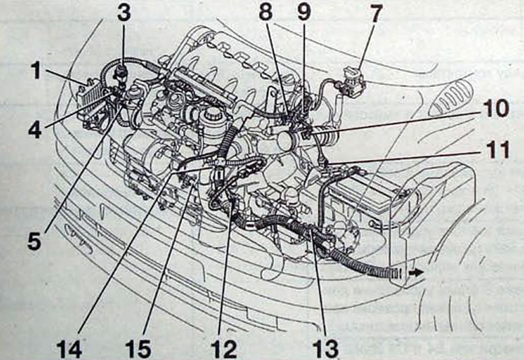
Pic. 3.21. Location of various engine management system components and wiring harnesses in the engine compartment with the G8T 716 engine: 1 - engine control unit; 3 - inertial shock sensor; 4 - fuel heater temperature sensor; 5 - electric fuel heater; 7 - EGR solenoid valve; 8 - coolant temperature sensor; 9 - coolant temperature indicator in the instrument cluster; 10 - air temperature sensor; 11 - speed sensor; 12 - speed sensor and crankshaft position; 13 - reverse light switch; 14 - solenoid valve for fast idle speed; 15 - temperature sensor of the air conditioning system
The pre- and post-heating function is controlled by an electronic unit.
The glow plug relay unit is integrated into the electronic control unit.
Turning on preheat
Preheating is carried out in two phases:
- A) variable preheating - depends on the coolant temperature at the moment the ignition is turned on (pic. 3.22).
- b) constant preheating. After the preheat indicator lamp (variable preheat) goes out, voltage is applied to the glow plugs for another 8.5 seconds before starting the engine. Starting the engine
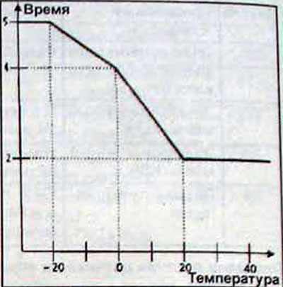
Pic. 3.22. Dependence of engine preheating turn-on time on coolant temperature in variable preheating mode
When the engine cranks with the starter, power supply voltage is supplied to the 4 glow plugs
Post-heating after engine start
Subsequent heating is carried out in two phases:
- A) constant post-heating. After starting the engine, voltage is applied to the glow plugs for another 10 seconds.
- b) variable afterheating. Variable afterheating begins when constant afterheating ends. The time for applying voltage to the glow plugs is 3 minutes.
Subsequent heating can be interrupted permanently if the coolant temperature exceeds 60°C or temporarily if the control unit receives a 60% load signal from the potentiometer for more than 3 seconds. in this case, the function is restored when switching to idle or low load mode.
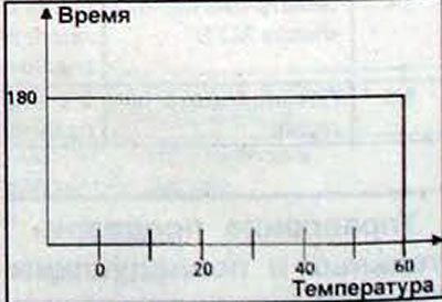
Pic. 3.23. Dependence of the engine heating switch-on time on the coolant temperature in the variable afterheating mode