Electrical power supply for G8T 714 motor
From the ignition switch, voltage is supplied to contact A1 of the engine control unit. This circuit is protected by a 30 A fuse (F38). located inside the car. The relay power circuit supplies voltage to the engine control unit (contact AZ connector) and protected by a 15 A fuse (F24) located inside the car.
After the ignition is switched on, power is supplied to the control unit through connector tracks 16 and 33, as well as through fast idle solenoid valve connector track 2, injection timing control solenoid valve track 1, ECR solenoid valve connector track 1 and engine preheater relay track 2.. The engine preheating system unit is supplied with a constant positive voltage through a 70 A fuse (fuse F49).
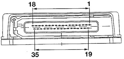
Pic. 3.17. G8T 714 Engine Control Unit Connector Pin Identification
| Contact no | Assigning Contacts |
| 1 | Nutrition (+5V) load potentiometer |
| 2 | Load potentiometer signal |
| 3 | Air temperature sensor signal |
| 4 | Coolant temperature sensor signal |
| 5 | EGR solenoid valve vacuum sensor signal |
| 6 | Diagnostics of short circuits in glow plug power supply circuits |
| 7 | Injector needle lift sensor signal |
| 8 | Crankshaft mode and position sensor signal |
| 9 | Diagnostic line |
| 10 | Not used |
| 11 | Not used |
| 12 | Monitoring the functioning of preheating |
| 13 | Not used |
| 14 | Power supply for the injection timing adjustment solenoid valve |
| 15 | EGR solenoid valve power supply |
| 16 | + 12 V APC |
| 17 | «Weight» |
| 18 | «Weight» |
| 19 | «Weight» load potentiometer |
| 20 | Nutrition (+5V) EGR solenoid valve vacuum sensor |
| 21 | «Weight» air and coolant temperature sensor |
| 22 | «Weight» EGR solenoid valve vacuum sensor |
| 23 | Shielding shell of the rotation speed and crankshaft position sensor and the injector needle lift sensor |
| 24 | «Weight» injector needle lift sensor |
| 25 | Rotation speed and crankshaft position sensor signal |
| 26 | Diagnostic line |
| 27 | Malfunction indicator lamp power supply |
| 28 | Fast idle solenoid valve power supply |
| 29 | Air conditioning compressor activation signal |
| 30 | Not used |
| 31 | Engine operating mode information |
| 32 | Glow plug power |
| 33 | + 12 V APC |
| 34 | «Weight» |
| 35 | «Weight» |
Electrical power supply for G8T 716 motor
From the ignition switch, voltage is supplied to contact A1 of the engine control unit, which powers the speed sensor. This circuit is protected by a 30 A fuse (F38), located inside the car.
The relay power circuit supplies voltage to the engine control unit (contact AZ connector) and protected by a 15 A fuse (F24), located inside the car.
After turning on the ignition, power is supplied to the control unit through contacts A4 of connector 2, as well as through contact 2 of the ECR solenoid valve connector. In the engine preheating system unit, a constant positive voltage is supplied through a 70 A fuse (fuse F49).
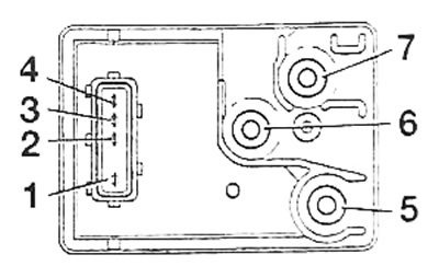
Pic. 3.18. G8T 714 Engine Preheat Relay Connector Pin Identification: 1 - «weight»; 2 - «+» ARS (after the ignition switch); 3 - glow plug relay control; 4 - short circuit of the glow plug power supply circuits; 5 - power supply to glow plugs 1-3; 6 - power supply to glow plugs 2-4; 7 - permanently energized
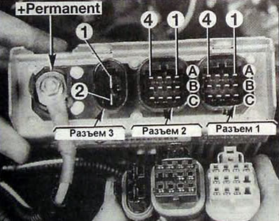
Pic. 3.19. G8T 716 Engine Control Unit Connector Pin Identification
| Contact no | Assigning Contacts |
| Connector No. 1 | |
| A1 | Load potentiometer signal |
| A2 | Air temperature sensor signal |
| AZ | Crankshaft mode and position sensor signal |
| A4 | Crankshaft mode and position sensor signal |
| IN 1 | Not used |
| AT 2 | Coolant temperature sensor signal |
| B3 | «Weight» air and coolant temperature sensor |
| AT 4 | «Weight» load potentiometer |
| C1 | Not used |
| C2 | Not used |
| NW | Nutrition (5 V) load potentiometer |
| C4 | Not used |
| Connector No. 2 | |
| A1 | Diagnostic line |
| A2 | + starter |
| AZ | «Weight» |
| A4 | + 12VARS |
| IN 1 | Air conditioning system information |
| AT 2 | KSB solenoid valve control (12 V) |
| VZ | Not used |
| AT 4 | Not used |
| C1 | Control «mass» engine warm-up indicator |
| C2 | Diagnostic line |
| NW | Control «mass» EGR valve |
| C4 | ALFB solenoid valve control |
| Connector No. 3 | |
| 1 | Power supply for glow plugs 1-3 |
| 2 | Power supply for glow plugs 2-4 |
Diagnostic tests
- Diagnostic tests below. refer to the vehicles described in this «Repair manual».
- The electrical characteristics of the components of the fuel system can be measured using a digital multimeter.
- To carry out the test, you must have basic skills in working with electronic equipment.
- Before starting the diagnostic test, a preliminary check must be performed.
- The check can only be carried out if you know the operating principle of the fuel system.
- The diagnostic test should begin with an analysis of the symptoms of the malfunction.
Preliminary checks
- Check the condition of the engine starting circuit: battery, power wires and starter.
- Check the condition of the engine preheating system.
- Check the condition of the fuses.
- Make sure there is enough fuel in the car's tank.
- Check the air supply system, the integrity and absence of damage to the air pipes, the tightness of the connections, the cleanliness of the air filter and its correct fit, as well as the reliability of the tightening of the clamps.
- Check the condition of the exhaust system: the tightness of the elements and their connections.
- Make sure engine mechanical parts are in good condition, valve timing is correct and the cylinder head gasket is sealed
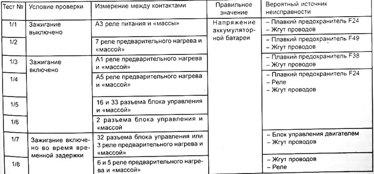
General power supply check
This check is as follows. to ensure that there is electrical power to the fuel system, which should be carried out with the connector connected to the engine control unit.
Engine G8T 714
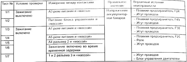
Engine G8T 716
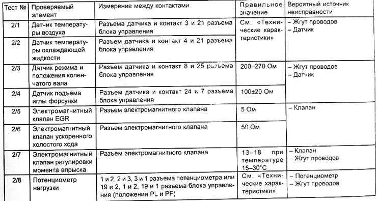
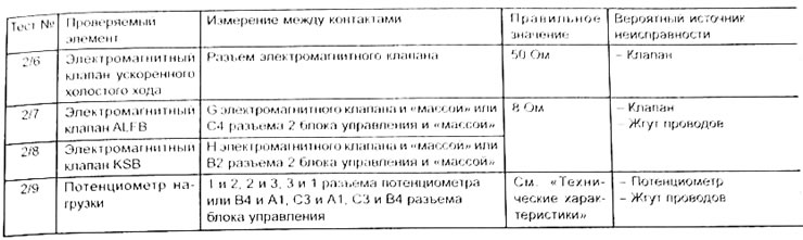
Checking sensors, solenoid valves and wires
This check consists of checking the condition of the fuel system peripherals, which must be carried out with the connector connected to the engine control unit. When checking, all connectors of peripheral devices must be connected to them.
Engine G8T 714
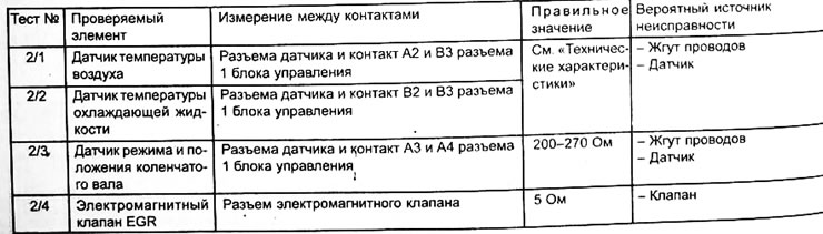
Engine G8T 716
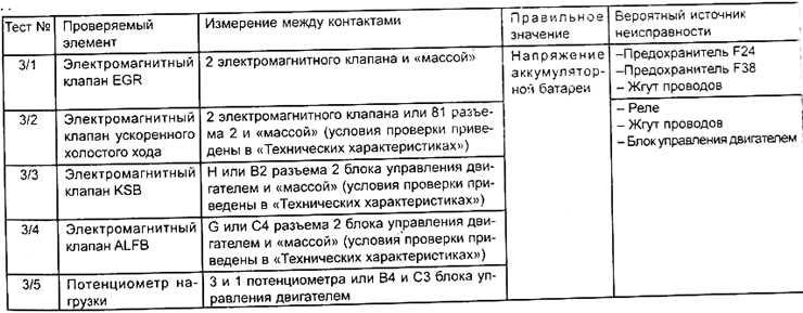
Checking the power supply of sensors and solenoid valves of the fuel system
This control consists of checking the supply voltage or sensor signal, which must be carried out with the connector connected to the engine control unit
Engine G8T 714
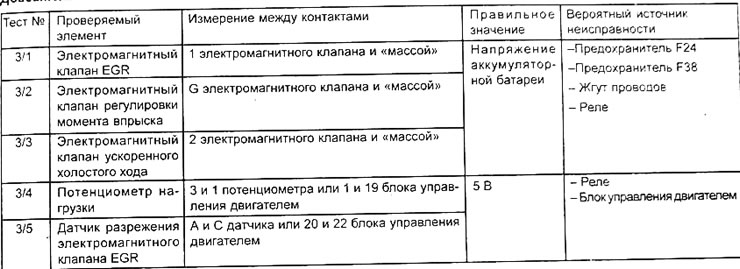
Engine G8T 716