



- Raise the car on a lift so that the wheels hang freely in the air.
- Disconnect the cable from the negative battery terminal.
- Remove the right front wheel, the plastic mudguard covering the engine and the right front wheel
- Set the piston of the first cylinder to TDC, and the mark on the camshaft pulley will be visible through the window of the timing belt cover.
- Using the special key Mot. 1383, disconnect the high pressure pipes.
- Remove the plug at the rear end of the high pressure distribution pump.
- Instead of the plug in the end of the high-pressure fuel pump, install a dial indicator with adapter Mot. 856, while ensuring that the measuring head of the indicator has a stroke of at least 1 mm in each direction.
- Using tool Mot. 1318 or a 7 mm diameter steel rod, lock the crankshaft by inserting the tool into the hole closed with a plug and located on the cylinder block between the flywheel and the oil filter (fig. 3.4).
- In this position, check the lift value of the high pressure fuel pump piston distributor.
- If the value is incorrect, it is necessary to adjust the injection timing of the high-pressure fuel pump.
- On vehicles with air conditioning, remove the A/C compressor pipe bracket from the fuel filter bracket.
- Remove the fuel filter and lift pump.
- Remove the three bolts securing the filter bracket.
- On vehicles with air conditioning, remove the upper accessory drive belt cover.
- Remove the high pressure fuel pump pulley housing.
- Install tool Mot. 1317, which locks the fuel pump pulley.
- Loosen the three fuel pump pulley mounting bolts on the bushing, then use the center nut to turn the bushing until the required reading is obtained on the dial indicator and tighten the bolts to the required torque
- Turn the engine crankshaft two full revolutions and check the fuel pump injection timing
- Remove the dial indicator and screw the plug back into place
- Special key Mot 1383 led, thread high pressure pipelines
- Tighten the three fuel pump pulley mounting bolts to the bushing to the specified torque.
- Remove the Mot 1317 high pressure pump pulley support tool
- Install the high pressure fuel pump pulley housing
- On vehicles with air conditioning, install the upper accessory drive belt cover.
- Install the fuel filter bracket.
- Install the fuel filter and booster pump, replacing the copper seals on the pipe connections
- On vehicles with air conditioning, install the A/C compressor pipe bracket onto the fuel filter bracket.
- Remove air from the fuel system.
- Connect the cable to the negative terminal of the battery.
- Install the plastic mudguard for the engine and right front wheel and the right front wheel
- Lower the car.
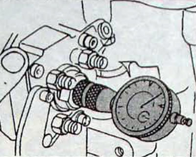
Fig. 3.10. Using a dial indicator to set the position of the fuel pump distributor piston in relation to the TDC of the 1st cylinder piston
Article reprinted from the website: www.RENAULTBOOK.ru
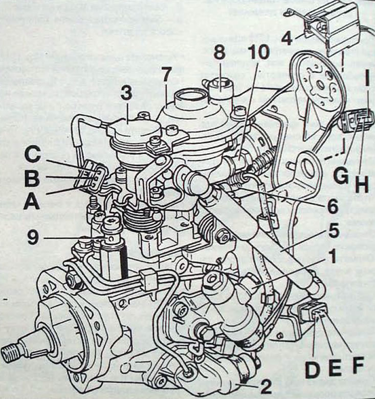
Fig. 3.11. High pressure fuel pump (g8T 716 engine): 1 - injection timing advance control solenoid valve (KSB); 2 - electromagnetic control valve depending on load (ALFB); 3 - load potentiometer; 4 - electronic block of the electromagnetic valve of blocking; 5 - deceleration shock absorber; 6 - screw for adjusting the maximum crankshaft speed; 7 - air boost capacity corrector; 8 - vacuum pipe; 9 - fuel pipe; 10 - fuel return pipe; A - "ground" of the load potentiometer supply; B - load lever signal; C - power supply for load potentiometer (5 V); D - blocking line; E - 12V power supply ARS; F - "mass"; G - solenoid valve dependent on load (ALFB); H - injection timing advance control solenoid valve (KSB); I - not used