
- Engine type - G8T714, G8T716
- Cylinder diameter, mm - 87
- Piston stroke, mm - 92
- Cylinder volume, cm3 - 2188
- Compression ratio - 22:1
- Maximum power:
- CEE - 83 kW at 4500 min-1
- DIN - 115 hp at 4500 min-1
- Maximum torque:
- CEE 23.4 daNm at 2000 min-1
- DIN 23.9 kgf-m at 2000 min-1
Cylinder head
The cylinder head is made of aluminum alloy and includes valve seats and guides, and pre-combustion chambers.
- Nominal height of the cylinder head between mating surfaces, mm - 147±0.08
- Maximum permissible deviation of the plane of the surface mating with the gasket, mm - 0.05
- Cylinder head regrinding - not provided
- Hole diameter for the combustion chamber, mm - 36.6-36.0.25
- Hole diameter for valve guide, mm - 12
Cylinder head gasket
The cylinder head gasket is made of two reinforced steel layers and has metal cylinder bore surrounds
- Thickness, mm - 1.75±0.05
Pre-combustion chambers
Pre-combustion chambers are installed in the cylinder head.
- Protrusion relative to the plane of the surface mating with the gasket, mm - 0-0.04
- Volume of the preliminary combustion chamber, cm3 - 6.5±0.2
Valve seats
Valve seats are pressed into the cylinder head
- Working chamfer width, mm - 1.55-1.90
- Working chamfer angle - 90°
Outer diameter, mm:
- intake valves - 32.6
- exhaust valves - 31.7
Valve guides
Valve guides are installed in the cylinder head and are sealed with oil seals
- Inner diameter, mm - 7
- External diameter, mm - 12.02-12.03
- Distance from the upper end of the guide bushing to the lower plane of the cylinder head, mm (see fig. 3.54) — 87,7 ±0,4
Valves
12 valves are installed perpendicular to the flattened surface of the cylinder head and parallel to each other, driven by the camshaft through rocker arms with hydraulic pushers
Working chamfer angle - 90°
Diameter of the plate, mm:
- intake valve 32.12
- exhaust valve 31.12
- Rod diameter, mm - 6.96-6.98
- Valve sinking, mm - 0.8-1.0
Valve lift, mm:
- intake valve - 10.50
- exhaust valve - 10.57
Valve springs
The intake and exhaust valve springs are identical
- Wire diameter, mm - 3.8
- Inner diameter, mm - 19±0.1
- Free length, mm - 48±2
- Length under load 27±1.35 daN,mm - 39.7
- Length under load 60.613 daN, mm - 29.2
- Length with fully compressed turns, mm - 27.7
Cylinder block
The engines use cylinder blocks made of cast iron with dry cylinder liners.
Cylinder liners.
- Cylinder diameter, mm - 87
Sleeve diameter, mm:
- class 1 - 87,000-87,015
- class 2 - 87.015-87.030
Simultaneous installation of class 1 and 2 pistons is prohibited
Moving parts of the engine
Crankshaft
The forged steel crankshaft has 4 counterweights and is supported by 5 main bearings.
- Radial clearance, mm - 0.042-0.215
- Axial play, mm - 0.060-0.230
- Diameter of connecting rod journals, mm - 47.975-47.991
- Diameter of main journals, mm - 57.98-58.00
- Basic thickness of feelers for adjusting axial play, mm - 2.3
- Regrinding of the crankshaft is not provided
Connecting rods
Steel I-section connecting rods with a lower split head and a hole for lubrication of the piston pin.
- Axial play, mm - 0.22-0.40
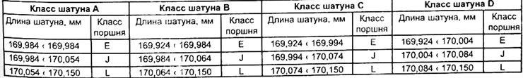
There are 4 classes of connecting rods with different distances between the axes of the upper and lower heads, mm:
- class A - 149.88-149.89
- class B - 149.89-149.90
- class C - 149.90-149.91
- class B - 149.91-149.92
- Axial play of connecting rods on crankpins, mm - 0.220-0.402
- Width of connecting rod bearing shells, mm - 20.40-20.65
Pistons
The pistons are made of aluminum alloy with internal lubrication and cooling provided by oil spray from jets located at the base of the cylinder liners.
Brand: Colmar
The piston crown includes a combustion chamber in the shape of a clover leaf.
- Piston protrusion, mm - 0.77 and 0.91
Diameter, mm:
- piston class No. 1 - 87,000-87,015
- piston class No. 2 - 87.015-87.030
Piston diameter, measured at a distance of 22 mm from the base of the skirt, mm - 86.910
Gap between piston and cylinder, mm:
- cylinders 1,2 and 3 - 0.090
- cylinder 4 - 0.100
| Mark on the piston | Height between the axle and the piston bottom, mm |
| E | 44,74-44,78 |
| F | 44,78-44,82 |
| J | 44,82-44,86 |
| TO | 44,86-44,90 |
| L | 44,90-44,94 |
| M | 44.94—44,98 |
Piston pins
The piston pins are made of case-hardened steel, of the floating type and are secured in the piston by two retaining rings.
Outer diameter, mm - 31
Length, mm - 70.60
Piston rings
Each piston has three piston rings
Piston ring thickness, mm:
- upper compression ring - 2.5
- second compression ring - 1.70
- oil scraper ring - 2.50
Installation - locks at an angle of 120°and a mark «TOP» up
Clearance in the lock - piston rings are supplied pre-adjusted, therefore it is not recommended to adjust the gaps in the locks of the rings
Flywheel
The dual-mass flywheel is made of cast iron and has a toothed ring. The flywheel is attached to the crankshaft flange with 7 bolts and in only one position. The flywheel consists of two disks connected by springs, this ensures their relative rotation by 80°.
Gas distribution mechanism
The gas distribution mechanism consists of a camshaft driven by a toothed belt
Valve timing
- Intake valve opening delay after TDC,°— 5
- Intake valve closing delay after BDC,°-5
- Exhaust valve opening advance to BDC,°- 22
- Exhaust valve closing advance to TDC,°- 5
Camshaft
The camshaft installed in the cylinder head rests on 5 support bearings (No. 1 from the timing gear drive side). The camshaft cams operate the valves via rocker arms and hydraulic lash adjusters (pushers)
Axial play, mm - 0.040-0.013
Timing belt drive of the gas distribution mechanism
Tension - automatic
Replacing the timing belt - every 120,000 km of vehicle mileage or every 5 years
Lubrication
The engine is lubricated under pressure by a pump driven by a chain from the crankshaft. A replaceable oil filter is used to clean the engine oil. Additional sprayers are used to lubricate and cool the pistons. The oil is cooled by a coolant/oil heat exchanger on vehicles without an air conditioning system and by an air/oil heat exchanger on vehicles with an air conditioning system located near the oil filter.
Oil pump
Minimum pressure created by the pump at an engine oil temperature of 80°C, bar:
- at 1000 min-1
- at 3000 min-1
Oil filter
- A replacement oil filter cleans the engine oil in the main line.
- Replacement frequency: every time you change the engine oil
Lubrication system
- Capacity (with filter replacement), l - 7.2
- Engine oil - SAE 10W40 or 15W40 specification CCMC-PD2 or ACEA B2-96/VZ-96
- Replacement frequency: every 15,000 km of vehicle mileage or every year
Cooling system
Closed-type liquid cooling system, using a mixture of antifreeze and water as the working fluid (for 4 seasons), and includes a radiator, expansion tank, water pump, thermostat and an electrically driven radiator fan controlled by a temperature sensor.
On vehicles with air conditioning, there are two electrically driven radiator fans.
Radiator
The radiator with horizontal tubes is made of aluminum alloy and has plastic tanks.
Expansion tank
The expansion tank is located in the upper right part of the engine compartment.
Opening pressure of the expansion tank plug, bar - 1.2
Thermostat
A thermostat with an expanding wax capsule is installed at the left end of the cylinder head.
- Starting temperature - 83°C
- Full opening temperature - 95°C
- Valve stroke, mm - 7.5
Electrically driven fan
Two electrically driven fans are located in front of the radiator.
Electrically driven fan temperature sensor
The temperature sensor is located in the lower left part of the radiator.
- Turn-on temperature - 83°C
- Shutdown temperature - 95°C
Water pump
The vane-type centrifugal water pump is driven from the crankshaft pulley by a timing belt.
Coolant
Capacity, l - 9
Recommended coolant: GLACEOL type D for frost protection down to -25°C
Coolant freezing temperature,°C:
- for countries with warm and temperate climates - -25
- for countries with cold climates - -37
Maintenance frequency - checking the level every 1,500 km of vehicle mileage
Replacement frequency: every 120,000 or every 4 years
Air filter
The air filter uses a replaceable paper filter element.
Replacement frequency: every 30,000 km of vehicle mileage
Glow plugs
Ultra-high-speed glow plugs with a temperature increase rate of up to 850°C in 3-7 seconds
- Brand - LUCAS or BERU-BOSCH
- Diameter, mm - 5
- Current consumption after 5 s of heating, A - 15
Preheater block
With pre- and post-heating function and control of KSB and ALFB valves
Type - NAGARES
Air boost
The air is pressurized by a turbocharger driven by the energy of the exhaust gases. The air charging system includes an air/air heat exchanger.
Turbocharger
Turbocharger with charge pressure control valve, the support of which can be cooled by coolant.
Make and type - GT17
Boost pressure to air-to-air heat exchanger, mbar
- at crankshaft speed 2000 min-1 750±50
- at crankshaft speed 4300 min-1 865±25
| Calibration pressure values, mbar | Valve stem movement, mm |
| 1115±45 | 1 |
| 1235±30 | 4 |
Fuel tank
The fuel tank is made of plastic.
Capacity, l - 80
Fuel - diesel
Fine fuel filter
The filter is equipped with an electric heater and a temperature sensor, which provides power to the heater depending on the fuel temperature.
The electric heater turns on when the fuel temperature is below 0±3°C and turns off when the fuel heats up to 8±3°C.
Heater power, W — 150
Brand – Purflux
Replacement frequency: every 30,000 km of vehicle mileage
Fuel pump
Engine G8T 714
Rotary pump with centrifugal electronic governor and pneumatic control of idle speed.
Brand and type - Bosch VE 4/9 F 2400 R708
Pump blocking when installing the piston of the 1st cylinder at TDC; the amount of lift of the pump plunger is 0.6±0.1 mm
Engine crankshaft speed, min-1
- at idle speed - 725±25
- at fast idle 850±25
Maximum engine crankshaft speed, min-1
- no load - 5,000±100
- with maximum load - 4,500±100
Smokiness:
- official value 2.88 ms-1
- maximum value 3 ms-1
Engine G8T 716
Rotary pump with a centrifugal mechanical regulator and an electromagnetic regulator for advancing the injection timing of a cold engine (KSB), controlled electromagnetically (ALFB) depending on the engine load and the engine preheating time delay unit.
Brand and type - without air conditioning system - Bosch R593 - with air conditioning system Bosch R593
Pump blocking when installing the piston of the 1st cylinder at TDC, the amount of lift of the pump plunger is 0.74±0.04 mm
Engine crankshaft speed, min-1:
- at idle speed - 725±25
- at fast idle - 850±25
Maximum engine crankshaft speed, min-1:
- no load 5,000±100
- with maximum load 4,500±100
Smokiness:
- official value 1.52 ms-1
- maximum value 2.5 ms-1
Injectors
Engine G8T 714
Brand and type - Bosch DN OSD 313
Opening pressure, bar - 145-160
Maximum permissible deviation, bar - 8
Injector body of the 1st cylinder - needle lift sensor Injector body of the 2nd, 3rd and 4th cylinders - Bosch KSA17 S103
Brand and type - Bosch KSA 17 S42
Dimensions of fuel supply pipelines, mm:
- outer diameter - 6
- internal diameter - 2.5
- -length
- cylinder No. 1 - 391
- cylinders No. 2,3,4 - 400
Engine G8T 716
Brand and type - Bosch DN OSD 313
Opening pressure, bar - 145-160
Maximum permissible deviation, bar - 8
Injector body - Bosch KSA 17 S42
Dimensions of fuel supply pipelines, mm:
- outer diameter - 6
- internal diameter - 2.5
- length - 400
G8T 714 engine management
The engine control unit
The engine control unit is located on the fender on the right side of the engine compartment. To comply with Euro 96 standards, the G8T 714 engine is equipped with a standard AS3.3 control unit. which performs the following functions:
- controls exhaust gas recirculation (EGR);
- controls glow plugs;
- controls the fast idle solenoid valve.
- controls fuel injection timing
Crankshaft position sensor
The inductive crankshaft position sensor is installed on the gearbox housing. It transmits information about the position of the crankshaft to the engine control unit to adjust engine operating parameters, activate EGR and accelerated idle.
- Number of pulses per revolution of the crankshaft - 4
- Resistance, Ohm - 200-270
Coolant temperature sensor
NTC Coolant Temperature Sensor (CTN) installed in the thermostat housing and has a white connector. It transmits information about the coolant temperature to the engine control unit.
Resistance, Ohm:
- at a temperature of 20°C - 3060-4045
- at a temperature of 40°C - 1315-1600
- at a temperature of 60°C - 670
- at a temperature of 80°C - 300-370
- at a temperature of 90°C - 210-270
Engine air temperature sensor Engine air temperature sensor with negative temperature coefficient (CTN) installed on the air filter housing duct. It transmits information to the engine control unit about the temperature of the air entering the engine.
Resistance, Ohm:
- at a temperature of 0°C - 7470-11970
- at a temperature of 20°C - 3060-4045
- at a temperature of 40°C - 1315-1600
- at a temperature of 60°C - 670
Accelerator pedal position potentiometer
The accelerator pedal position potentiometer transmits to the control unit a voltage signal directly proportional to the angular position of the accelerator pedal, which determines the engine load. It is powered by 5 V from the control unit and is mounted on the high pressure fuel pump.
Output voltage of the sensor with the accelerator pedal fully pressed, V - 4.5±0.1
Type - Bosch
Atmospheric pressure sensor
A sensor connected to the control unit measures atmospheric pressure
Needle lift sensor
The needle lift sensor installed on the injector of the first cylinder transmits a signal to the control unit about the start of fuel injection, on the basis of which the fuel injection timing is adjusted.
Resistance, Ohm — 100±20
Fast idle solenoid valve The fast idle solenoid valve is located above the starter. It controls the vacuum of the fast idle system by connecting it to the vacuum pump. The fast idle system is activated if the following three conditions are met simultaneously - the engine is running
- crankshaft rotation speed - less than 1350 min-1
- coolant temperature - less than 44°C
Resistance, Ohm — 50
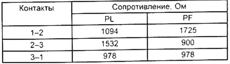
Solenoid valve for adjusting injection timing advance
The valve allows you to regulate the timing of fuel injection and thus fuel injection depending on the mode, load and coolant temperature.
The valve is located under the high pressure pump and is connected by a three-pin GHI connector. The value is maximum if the valve is not powered.
Resistance between contacts, Ohm:
- at a temperature of 15-30°C - 13-18
- at a temperature of 50-70°C - 14-22
EGR solenoid valve
The EGR solenoid valve is controlled by the engine control unit and connects the vacuum created by the vacuum pump and the EGR system. This determines the amount of exhaust gas supplied to the intake system depending on the opening of the solenoid valve. RCO type system (cyclic opening) opens the -GR valve when current passes through the solenoid valve.
- 1.1 Amps - full open
- 0 Ampere - full shutdown
- Resistance, Ohm - 5
EGR solenoid valve vacuum sensor
The sensor is installed on the control circuit and transmits information to the control unit about the average pressure applied to the EGR valve.
Glow plug relay
The glow plug relay is located in the housing above the engine control unit and controls engine preheating. The relay supplies voltage to the two glow plugs (1-3) And (2-4).
G8T 716 Engine Management
The engine control unit
The engine control unit is located on the right side of the engine compartment near the fine fuel filter. To comply with Euro 96 standards, the G8T 716 engine is equipped with a T.R.R. device. -EGR (Time delay for engine preheating and Sagem EGR control unit) The control unit performs the following functions:
- controls exhaust gas recirculation (EGR);
- activates on the KSB pump (electromagnetic regulators for advancing the injection timing of a cold engine) and ALFB transition to low load and deceleration);
- controls glow plugs (1-3 and 2-4);
- controls the fast idle solenoid valve.
Crankshaft position sensor
The electromagnetic crankshaft position sensor is installed on the gearbox housing.
It transmits information to the engine control unit about the position of the crankshaft to adjust the timing of fuel injection and activate EGR.
Resistance, Ohm - 200-270
Coolant Temperature Sensor NTC Coolant Temperature Sensor (CTN) installed in the thermostat housing and has a white connector. It transmits information about coolant temperatures to the engine control unit.
Resistance, Ohm:
- at a temperature of 20°C - 3060-4045
- at a temperature of 40°C - 4315-1600
- at a temperature of 60°C - 670
- at a temperature of 80°C -300-370
- at a temperature of 90°C - 210-270
Temperature sensor for air entering the engine.
Engine air temperature sensor with negative temperature coefficient (CTN) installed on the air filter housing duct. It transmits information to the engine control unit about the temperature of the air entering the engine.
Resistance, Ohm:
- at a temperature of 0°C - 7470-11970
- at a temperature of 20°C - 3060-4045
- at a temperature of 40°C - 1315-1600
- at a temperature of 60°C - 1200
Accelerator pedal position potentiometer
The accelerator pedal position potentiometer transmits to the control unit a voltage signal directly proportional to the angular position of the accelerator pedal, which determines the engine load. It is powered by 5 V from the control unit and is mounted on the high pressure fuel pump.
Output voltage of the sensor with the accelerator pedal fully pressed, V - 4.5±0.1
Type - Bosch
Contact Resistance Values - See G8T714 Motor
Atmospheric pressure sensor
A sensor connected to the control unit measures atmospheric pressure.
Solenoid valve for adjusting injection timing advance KSB
The solenoid valve for adjusting the injection timing of a cold engine KSB is controlled by the engine control unit. It is activated by applying voltage for a minimum of 8 seconds after start-up, then it is activated or deactivated depending on various parameters:
- the air temperature when the ignition is turned on is in the range of 10-50°C;
- in the upper part, activation of the KSB, depending on the o-air temperature, occurs much later, so the activation time of the solenoid valve is increased;
- In all cases, KSB is deactivated if the crankshaft speed exceeds 2250 rpm-1 and when the engine is running at full load.
Supply voltage, V - 12
Solenoid valve resistance, Ohm - 8
Fast idle solenoid valve The fast idle solenoid valve is located above the starter and is controlled by the engine control unit. It controls the vacuum of the fast idle system by connecting it to the vacuum pump. This relationship is only present on engines installed in vehicles with air conditioning. When voltage is applied, the fast idle system is activated if the air temperature is below 10°C. The function will be canceled as soon as the coolant temperature rises to 60°C.
Resistance, Ohm — 50
Load dependent engine control solenoid valve ALFB
Dependence on hydraulic load (LFB) aims to convert pressure into a voltage signal during deceleration and low load in order to reduce fuel consumption. Solenoid valve (AFLB), controlled by the engine control unit, is a device that overrides the functioning of the LFB when the engine is cold.
The functioning of the ALFB depends on various parameters:
- air temperature when the ignition is turned on;
- in the upper part, activation of ALFB, depending on air temperature, occurs much later. Thus, the excitation time of the solenoid valve is increased;
- load and engine speed: for reasons of pollution and noise removal, AFLB is activated: - if the coolant temperature is between 65°C and 80°C;
- if the engine speed is between 1350 and 1900 min-1;
- In all cases, ALFB is deactivated if the engine speed exceeds 3050 rpm-1 when the engine is running at full load.
Supply voltage, V - 12
EGR solenoid valve
The EGR solenoid valve is controlled by the engine control unit and connects the vacuum created by the vacuum pump and the EGR system. This determines the amount of exhaust gas supplied to the intake system depending on engine load, engine speed, intake manifold pressure and air and coolant temperatures. RCO type system (cyclic opening) opens the EGR valve when current flows through the solenoid valve.
- 1.1 Amps - full open
- 0 Ampere - full shutdown
- Between 0 and 1.1 - Ampere partial opening
Resistance, Ohm - 5
In all cases, the EGR solenoid valve is inactive if.
- air temperature less than 19°C;
- coolant temperature less than 40°C;
- the car slowly stops for 20 seconds.
Glow plug relay
The glow plug relay is located in the housing above the engine control unit and controls engine preheating and the solenoid valves KSB and ALFB. The relay supplies voltage to the two glow plugs (1-3) And (2-4).
Brand – Nagares
Consumables
| Name | Quantity | Place of application |
| Rhodorseal 5661 | Sufficient for lubrication | holes for installing drive shaft pins |
| Loctite FRENBLOC Sealant | Sufficient for lubrication | Brake caliper mounting bolts |
| Loctite FRENETANCH Sealant | Sufficient for lubrication | Crankshaft pulley bolt |
| MOLYKOTE BR 2 Paste for sealing pipe joints in exhaust gas systems | Sufficient for lubrication | Mounting protrusion on the hub under the central hole of the wheel rim |
Tightening torques, Nm
Cylinder head bolts (the threads and base of the head must be lubricated with engine oil), tightening sequence from 1 to 18":
Stage 1 - 20 Nm
Stage 2 - turn the corner:
- number 1,5,9,13,17 — 215± 2°
- number 2, 6,10,14,18 — 240± 2°
- number 3, 7,11,15 — 160±2°
- number 4,8,12,16 — 246± 2°
Stage 3 wait three minutes for the gasket to stabilize
4th stage:
- loosen bolts 1 and 2 completely
- tighten the bolts to 20 Nm, then bolt 1 - 296±2°and bolt 2 - 301±2°
- loosen bolts 3, 4, 5, 6 completely
- tighten the bolts to 20 Nm, then bolt 3 - 243±2°,
- bolt 4 - 322±2°, bolt 5 - 296±2°and bolt 6 - 301±2°,
- Loosen bolts 7, 8, 9,10 completely,
- tighten the bolts to 20 Nm, then bolt 7 - 243±2°,
- bolt 8 - 32212°, bolt 9 - 296±2°and bolt 10 - 301±2°,
- Loosen bolts 11, 12, 13, 14 completely,
- tighten the bolts - 20 Nm, then bolt 11 - 243±2°, bolt 12 - 322±2°, bolt 13 - 296±2°and bolt 14-301±2°,
- Loosen bolts 15, 16, 17, 18 completely,
- tighten the bolts - 20 N−m, then bolt 15 - 243±2°, bolt 16 - 322±2°, bolt 17 - 296±2°and bolt 18 - 301±2°.
- Cylinder head cover - 9
- Camshaft support - 21
- Camshaft pulley* - 20 Nm + 90°
- Vacuum pump - 22
- Timing belt tensioner roller - 30
- Crankshaft pulley (with Loctite Auloform) * — 25 Nm + 64±6°
- Gear belt casings of the gas distribution mechanism — 9
- Connecting rod lower cover* — 20 Nm +70°
- Oil pump - 19-23
- Oil sump - 9
- Oil pump sprocket - 9
- Front crankshaft cover - 9
Crankshaft main bearing cap housing:
- central bolts 20 Nm +140°
- external bolts - 21
- Flywheel* — 60
- Water pump - 20
- Intake manifold - 22
- Intake manifold mounting studs 6±2
- Turbine engine control valve bracket (with Loctite Autoform) — 15
Connections of turbine engine cooling system elements
- entrance – 15
- output - 10
- Connections of elements of the turbine engine lubrication system - 20
- Turbocharger to exhaust manifold - 28
- Turbocharger outlet pipe - 26
- Support bracket for turbocharger and exhaust pipe - 21
- Exhaust manifold to cylinder head - 19
- Turbine engine thermal screen - 9
- High pressure pump - 22
- Fastening the high-pressure pump pulley to the bushing - 22
- High pressure pump support bracket - 22
- High pressure pump pulley - 90
- High pressure piping connections to high pressure pump - 25
- Injector body to cylinder head - 70±10
- Lower nozzle body - 80±10
- Glow plugs - 20
- Heater spiral nut - 4
- Stop spiral nut - 2
- Accessory drive belt tensioner roller - 56
- Tensioner roller for accessory drive belt - 40
- Bolt for fastening the pendulum suspension bracket - 50-65
- Bolt securing the front right pendulum suspension bracket to the engine - 48-65
- Bolt securing the pendulum suspension to the gearbox - 55-65
- Bolt for fastening the travel stop of the pendulum suspension - 50-55
- Bolts for fastening the corrugated protective cover of the drive shaft - 25
- Tie rod mounting bolts - 120-180
- Bolts of the lower fastening of shock-absorbing struts M16x200 - 200
- Upper nut for securing the pendulum suspension cushion on the front left side member - 55-80
- Tie rod end mounting nut - 40
- Lower ball joint fastening nut - 55
- Nut of the front right pendulum suspension bracket - 30-45
- Lower nut securing the pendulum suspension cushion on the front left side member - 100-125
- Swivel nut - 20
- Catalytic converter inlet flange mounting nut - 22
- Nut securing the repair pipe of the exhaust gas system - 25
- Wheel bolts - 100
*When installing, you must use new bolts