
Disassembly
Attention. When disassembling the cylinder head, make sure that all parts can subsequently be installed in their original places.
- Remove the glow plugs.
- Remove the exhaust manifold and turbocharger.
- Using the Renault Mot 799 tool, block the camshaft from turning, unscrew the bolt and remove the pulley from the camshaft.
- Remove the vacuum pump.
- Remove the coolant housing located at the end of the cylinder head.
- Unscrew the bolts and remove the camshaft bearing caps.
- Remove the oil seal and camshaft.
- Remove the valve rocker arms and remove the hydraulic valve lash adjusters from their sockets.
- Using a valve spring compressor, compress the first valve spring and remove the retainers.
- Smoothly loosen the spring compression device and remove it.
- Remove the upper spring plate, spring, lower spring plate and valve from the cylinder head
- Using appropriate pliers, remove the oil seal from the valve guide.
- Remove the remaining valves in the same way.
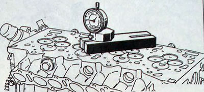
Pic. 3.53. Using a dial indicator with a Renault Mot bracket. 251-01 for measuring the protrusion of the preliminary combustion chambers
- Remove the pre-combustion chambers. If necessary, squeeze them out using a stream of appropriate fluid or Renault B.Vi. 31-01, supplied through the hole for installing the nozzle.
Attention. The pre-combustion chambers can be installed freely, so do not drop them when removing the cylinder head.
Checking the cylinder head
- Check that the mating surface of the cylinder head is not scratched and there are no burn marks.
- Using a steel straight edge and a feeler gauge or dial indicator, check the flatness of the bottom surface of the cylinder head. If the head is deformed, replace it as the head cannot be reground.
- Dial indicator with Renault Mot bracket. 251-01 or Mot 252-01 check the protrusion of the pre-combustion chambers.
- Measure the distances from the upper ends of the guide bushings to the bottom plane of the cylinder head.
Note. To avoid changes in the volume of the combustion chambers, only minor processing of the valve seats is necessary.
- The valve seats are pressed into the cylinder head. After replacing the valve seats, they must be processed on a milling machine. Working chamfer (1, fig. 3.55) processed with milling cutter No. 230 at an angle of 45°. Reduce the width of this chamfer until you get the width (X) chamfer processing (2) cutter No. 211 with an angle of 65°for the intake valves and cutter No. 605 with an angle of 65°for the exhaust valves.
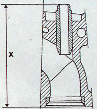
Pic. 3.54. Location for measuring the distance from the upper end of the guide bushing to the lower plane of the cylinder head
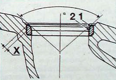
Pic. 3.55. Treatment of valve seats: X is the width of the working chamfer; 1 and 2 - processed chamfers
Note. After machining the valve seats, be sure to grind the valves.
- Check the smooth movement of the valve stems in the valve guides. %
- Check the calibration of the springs and, if necessary, replace them.
Cylinder head assembly
- Clean the cylinder head and all parts installed in the cylinder head
- Replace worn parts.
- Check the cleanliness of the grease supply holes to the camshaft bearings.
- Check the presence of a drain valve on the camshaft bearing support on the vacuum pump side.
- Lubricate the first valve stem with engine oil and insert it into the guide.
- Install the oil deflector cap using a tubular mandrel.
- Install the lower spring seat, spring and upper spring seat.
- Compress the valve spring with a spring compressor and insert the cotters into the top of the valve stem.
- Smoothly remove the spring compressor and check that the crackers are in place.
- Install the remaining valves in the cylinder head in the same way.
- Once all the valves are in place, lightly tap the top of the valve springs with a plastic hammer. to make sure the crackers are in place.
- Dial indicator with Renault Mot bracket. 251-01 or Mot 252-01, check the recessing of the valves in relation to the mating surface of the cylinder head.
- Install the preliminary combustion chambers and use a dial indicator to measure their protrusion from the cylinder head.
- Install hydraulic valve lash adjusters and rocker arms.
- Install the camshaft.
Note. If new hydraulic valve lash adjusters are installed, tighten the camshaft bearing caps gradually on all five bearings.
- If hydraulic valve lash adjusters have already been installed, after tightening the camshaft bearing cap bolts, all valves will be open. In this case, it is prohibited to turn the camshaft for 16-20 minutes. After installing the cylinder head, it is necessary to start the engine for 5-10 minutes at a crankshaft speed of 2500 min-1.
- Tighten the camshaft bearing cap bolts to the required torque and measure the axial play of the camshaft using a dial indicator and the corresponding bracket.
- Renault Mot. 1315 replace the camshaft oil seal.
- Install the camshaft pulley using the Renault Mot. 799 block the pulley from turning, screw in and tighten the pulley mounting bolt to the required torque.
- Further assembly of the cylinder head is carried out in the reverse order of disassembly, and it is necessary to observe the tightening torques of the threaded connections.
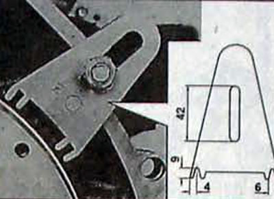
Pic. 3.56. Using the Renault Mot. 1316 to block the flywheel from turning