
Disassembly
- Remove the power unit from the vehicle.
- Remove the cylinder head.
- Disconnect the electrical connectors from the starter, remove the bolts and remove the starter.
- Remove the bolts securing the gearbox to the engine.
- Separate the gearbox from the engine.
- Remove the clutch cover with pressure plate and the driven disc.
- Use the Renault Mot 1316 tool to block the flywheel from turning.
- Remove the power steering pump.
- Remove the high pressure fuel pump.
- Disconnect the electrical connectors and remove the generator.
- Remove the attachment bracket.
- If the vehicle is equipped with an air conditioning system, remove the compressor.
- Remove the water pump mounting bolts.
- Remove the pulley, key and spacer from the crankshaft.
- Remove the oil sump.
- Remove the guide tube of the dipstick to measure the engine oil level.
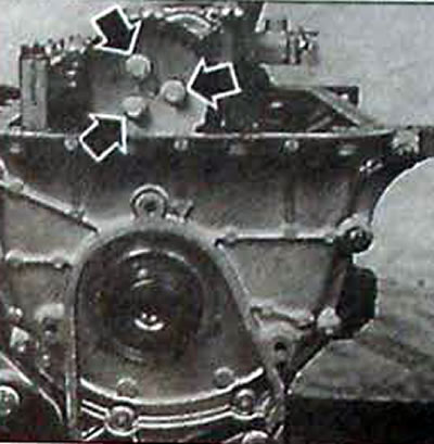
Pic. 3.57. Location of oil pump sprocket bolts
- Remove the engine oil return pipe.
- Remove the front cylinder block cover and remove the crankshaft oil seal.
- Remove the three bolts and sprocket from the oil pump.
- Remove the oil pump, while paying attention to the location of the gasket.
- Remove the oil filter and coolant/engine oil heat exchanger bracket
- Unscrew the bolts and remove the crankcase support and main bearing shells.
- Unscrew the bolts and remove the connecting rod caps and connecting rod bearing shells.
- Remove the crankshaft, main bearing shells and thrust washers that limit crankshaft end play.
- Remove the pistons with connecting rods from the cylinder block. Cylinder No. 1 is located on the flywheel drive side.
- Remove the engine oil sprayers on the pistons.
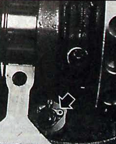
Pic. 3.58. Location of the engine oil sprayer on the pistons
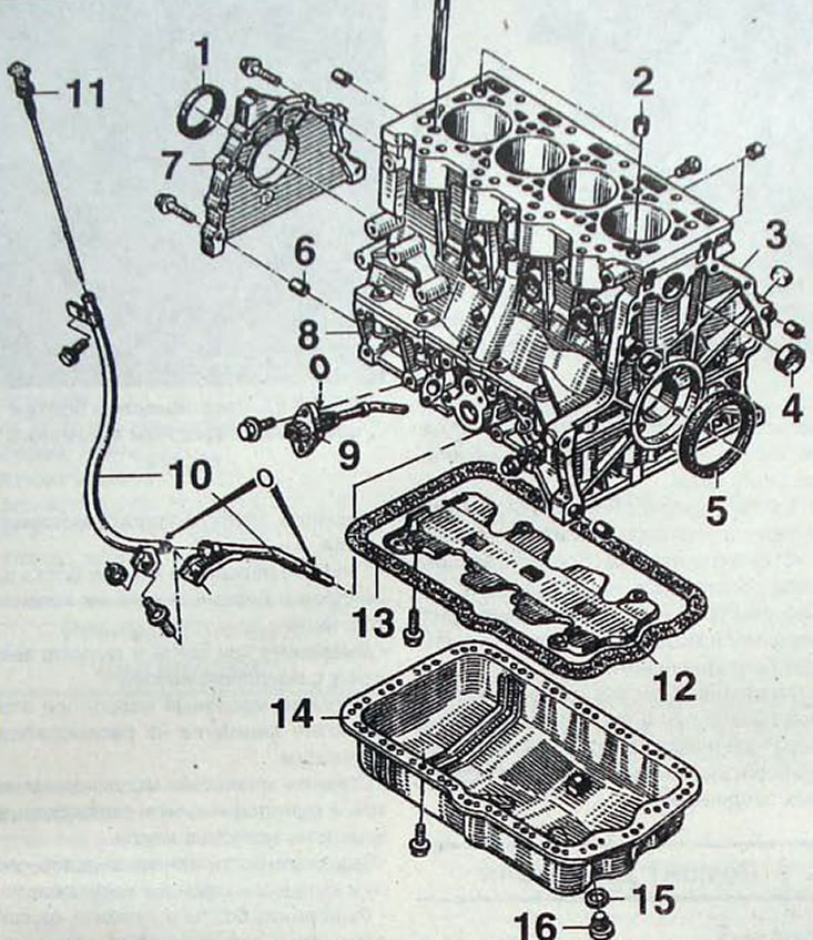
Pic. 3.59. Cylinder block: 1 - oil seal; 2 - centering sleeve; 3 - cylinder block; 4 - plug; 5 - oil seal; 6 - centering sleeve; 7 - front cover; 8 - crankshaft support housing; 9 - oil level sensor; 10 - dipstick guide tube for measuring the engine oil level; 11 - dipstick for measuring engine oil level; 12 - oil reflector; 13 - oil pan gasket; 14 - oil pan; 15 - sealing ring; 16 - oil drain plug
Assembly
- Thoroughly clean the gasket mating surfaces. This operation should be performed carefully to avoid foreign particles from entering the pressurized oil supply channel system.
- Use a wire to clean the oil passages.
- Install engine oil sprayers on the pistons.
Checking the cylinder block
- Using a dial indicator, measure the diameters of the cylinders in two diametrically opposite directions and at different heights.
- Check the condition and flatness of the surface of the cylinder block mating to the cylinder head gasket.
Note. Regrinding of the cylinder block is not provided; therefore, if necessary, replace the cylinder block.
Checking the radial clearance of the crankshaft main bearings
- Wipe the outer parts of the main bearing shells and their installation locations in the cylinder block. Insert the upper main bearing shells into the cylinder block without lubrication
- Clean the crankshaft journals and install it into the cylinder block.
- Cut a piece of plastic calibrated plastigage rod the length of which is equal to the width of the bearing, and lay it along the axis of the crankshaft on the main bearing journal.
- Install the crankshaft support housing with the main bearing shells and secure with bolts, tightening them to the required torque. Do not wrench the crankshaft
- Unscrew the bolts and remove the crankshaft support housing
- Compare the width of the deformed plastic rod with the measuring scale printed on the packaging of the plastic rod. Determine the radial clearance using the scale. If the radial clearance does not correspond to the required value, replace the crankshaft main bearing shells
Checking the crankshaft end play
- Clean the working surfaces of the main bearing shells and lubricate them with a thin layer of engine oil. Also lubricate the working surface of the crankshaft thrust half ring
- Install the crankshaft support housing with the main bearing shells and secure with bolts, tightening them to the required torque.
- Make sure the crankshaft rotates easily and freely.
- Install a dial gauge on a magnetic stand and check the crankshaft end play.
- The axial play of the crankshaft is determined by the thickness of the thrust rings installed on the crankshaft support on the flywheel side.
Checking and assembling pistons and connecting rods
- Remove the piston rings from the pistons
- Check the clearances in the piston ring locks. To check the gap in the ring lock, remove the ring from the piston, insert it into the cylinder liner and push the piston into the middle part of the working area of the cylinder. Use a feeler gauge to measure the gap in the ring lock
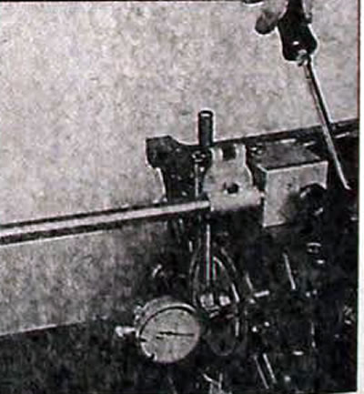
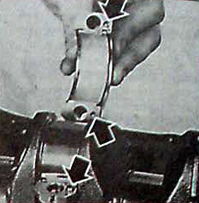
Pic. 3.60. Using a Dial Indicator to Measure Crankshaft Endplay
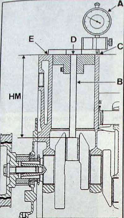
Pic. 3.61. Using the Renault Mot.1319 tool to determine the connecting rod height: A - dial indicator; NM - connecting rod length; B - rod; E, D, C - places of change
- Remove the pistons from the connecting rods by removing one retaining ring at a time and pressing out the piston pin.
- Measure the diameter of the piston pin in two mutually perpendicular directions.
- Check the condition of the bushings in the upper connecting rod heads.
- Check the condition and shape of the connecting rod and, if necessary, repair or replace it.
- Measure the length of the connecting rod.
Note
- When replacing pistons, connecting rods, cylinder block or crankshaft, it is necessary to determine the length of the connecting rod HM, which will allow you to select a piston in accordance with the connecting rod.
- The connecting rod length must be measured using the Renault Mot tool. 1319.
- The pistons of cylinders No. 1 and 4 are installed at TDC using the usual method, and the pistons of cylinders No. 2 and 3 are installed at TDC using a dial gauge
- Install the Renault Mot.1319 tool in place of the piston, connecting rod and connecting rod bearing.
- Install the dial indicator (A. Fig 3 61) on the cylinder block and after measuring dimensions (WITH) And (E) calculate the average.
- For cylinders No. 1 and 4, measure protrusion (D) rod (IN).
- For cylinders No. 2 and 3, rotate the crankshaft and determine the top dead center of the connecting rod journal and measure the protrusion (D) rod (IN).
Note
- Rod length (IN) marked on the box of the Renault Mot.1319 fixture and is equal to 170.114 mm. Connecting rod length NM = rod length (IN) - performance (D).
- Example of connecting rod length calculation (NM).
| Cylinder | №1 | №2 | №3 | №4 |
| Protrusion D, mm | 0,115 | 0,125 | 0,130 | 0,095 |
NM = 170.114 - 0.115 = 169.999 for cylinder No. 1
NM = 169.989 for cylinder No. 2
NM = 169.984 for cylinder No. 3
NM = 170.019 for cylinder No. 4
- Select a piston that matches the connecting rod length.
- Lubricate the piston pin
- Check that the piston pin rotates easily and smoothly in the piston and connecting rod
- The piston and connecting rod must be assembled while respecting their relative position:
- the groove on the piston skirt and the engine oil sprayer must be located on the flywheel side of the engine;
- protrusions (A, fig. 3.63) on the connecting rod and the lower head of the connecting rod should be located on the side of the clover-shaped recesses on the piston bottom.
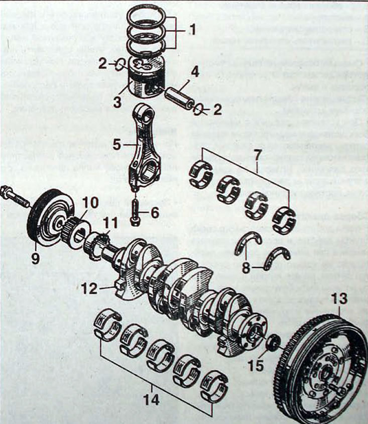
Pic. 3.62. Crankshaft and pistons: 1 - piston rings; 2 - retaining ring; 3 - piston; 4 - piston pin; 5 - connecting rod; 6 - connecting rod cover fastening bolt; 7 - connecting rod bearing shells; 8 - thrust half-rings for adjusting the axial play of the crankshaft; 9 - crankshaft pulley for drive of mounted units; 10 - crankshaft pulley of the gas distribution mechanism drive; 11 - oil pump drive sprocket; 12 - crankshaft; 13 - dual-mass flywheel; 14 - main bearing shells; 15 - bearing;
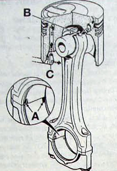
Pic. 3.63. The relative position of the piston and connecting rod assembly: A - protrusions;; B - hole for lubrication;; C - engine oil sprayer
- Lubricate the piston pins with clean engine oil and install them into the piston and connecting rod.
- Secure the piston pins with retaining rings.
- When installing a piston with a connecting rod into the cylinder block, the markings on the connecting rods should be located on the side opposite the high-pressure fuel pump. The pins on the connecting rod caps should be located on the side opposite the flywheel.
Engine assembly
- To achieve maximum engine life after a major overhaul with a minimum of problems, not only must all parts be assembled correctly, but all parts and components must be spotlessly clean, all lube passages must be clean, lock washers and spring washers must be in place.
- Using special pliers, install the piston rings on the piston in the following sequence:
- oil scraper ring;
- 2nd compression ring;
- 1st compression ring.
- When installed correctly, the piston rings should move freely in their grooves.
- If rings that were previously installed are installed on the piston, then they must be installed in their original places.
- Check the installation direction of the piston rings, marks «TOP» should be directed towards the piston crown.
- Move the piston ring locks at an angle of 120°, and neither lock should coincide with the piston pin axis.
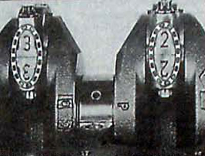
Pic. 3.64. Location of marks on the connecting rod and connecting rod cover
- Lubricate the piston and piston rings with engine oil. Install the Facom 750 TV universal piston ring compressor and get ready to install the piston into the cylinder liner.
- Install the piston from the top side of the cylinder by carefully but firmly tapping the piston with the handle of a hammer to install the piston into the cylinder liner. When installing a piston with a connecting rod into the cylinder block, the marks on the connecting rods should be located on the side opposite the high-pressure fuel pump.
Attention. When installing pistons and connecting rods, orient them correctly to avoid damage to the engine oil nozzles.
- Check the radial clearances between the connecting rod bearing shells and the crankshaft journals in the same way as checking the radial clearance of the crankshaft main bearings. If necessary, replace the connecting rod bearing shells.
Pic. 3.65. Location of pins on the connecting rod and connecting rod cap
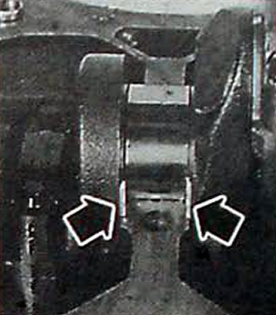
Pic. 3.66. Location of the thrust half-rings for adjusting the axial play of the crankshaft
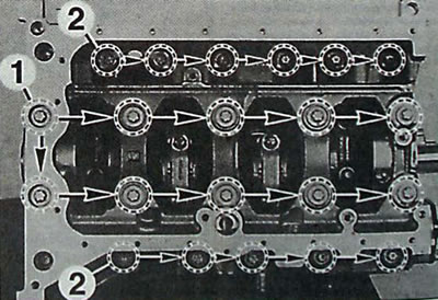
Pic. 3.67. Sequence of tightening the crankshaft housing mounting bolts: 1 - internal fonts; 2 - external bolts
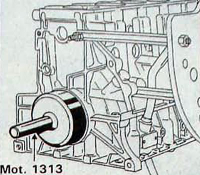
Pic. 3.68. Using the Renault Mot. 1313 for installing the front crankshaft oil seal
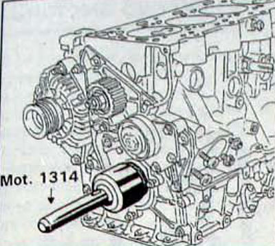
Pic. 3.69. Using the Renault Mot. 1314 for installing the rear crankshaft oil seal
- Wipe the outer parts of the main bearing shells and their installation locations in the cylinder block. Insert the upper main bearing shells into the cylinder block without lubrication. Clean the working surfaces of the main bearing shells and lubricate them with a thin layer of engine oil.
- Install the crankshaft with the upper thrust half rings on the bearing support on the flywheel side.
- Install the connecting rod bearing shells into the connecting rod and connecting rod cap.
- Install the connecting rod to the crankshaft, then install the connecting rod cap and secure with bolts, tightening them to the required torque.
- Apply Rhodorseal 5661 to the lower mating surface of the cylinder block.
- Install the crankshaft support housing with the main bearing shells and secure with bolts, tightening them in a certain sequence to the required torque
- Using a dial indicator with the appropriate bracket, measure the protrusion of the pistons from the cylinder block.
- Apply Rhodorseal 5661 paste to the cylinder block mating surface of the front cover, install the front cover and secure with bolts, tightening them to the required torque.
- Lubricate the working edges of the crankshaft front oil seal with engine oil and use the Renault Mot. 1313 install it into the front cover.
- Lubricate the working edges of the crankshaft rear oil seal with engine oil and use the Renault Mot. 1314 install it into the cylinder block.
- Make sure the crankshaft rotates freely.
- Install the flywheel and secure with bolts, tightening them to the required torque.
- Fill the internal cavities of the oil pump with engine oil.
- Install the oil pump.
- Install the oil return pipe.
- Install the oil pan with a new gasket and secure with bolts, tightening them to the required torque.
- Degrease the mating surface of the water pump.
- Apply Rhodorseal 5661 to the water pump mating surface, install and bolt the pump. tightening them to the required torque.
- Further assembly is carried out in the reverse order of disassembly.