
Attention:
It is strictly forbidden to apply any pressure to the engine oil pan. Damage to the sump can also cause various damage to the engine itself due to:
- blocking the oil intake;
- increasing the engine oil level above the maximum mark, which can cause the engine to run wild.
Disassembly
1. Drain the coolant and. engine cooling systems.
2. Remove the air filter unit,
3. Remove the attachment drive belt.
4. Remove the crankshaft pulley.
5. Remove the timing belt.
6. Remove rocker cover.
7. Remove the cylinder head from the engine.
8. Install the cylinder head on a special stand (Mot. 1573)
9. Remove the lifting eye from the flywheel side (1).
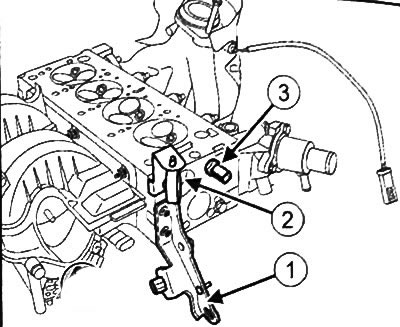
10. Remove wiring mounting bracket (2).
11. Remove the coolant temperature sensor (3).
12. Remove the throttle valve.
13. Remove the fuel rail.
14. Remove intake manifold.
15. Remove the spark plugs.
16. Remove the water chamber of the cylinder head.
17. Loosen the bolts (4) lifting eye on the timing drive side.
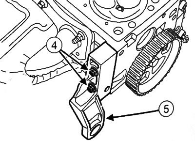
18. Remove the lifting eye from the timing drive side (5).
19. Remove the exhaust manifold.
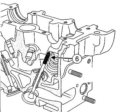
20. With a toothed pulley lock (Mot. 799-01) unscrew the bolt (6) camshaft pulley.
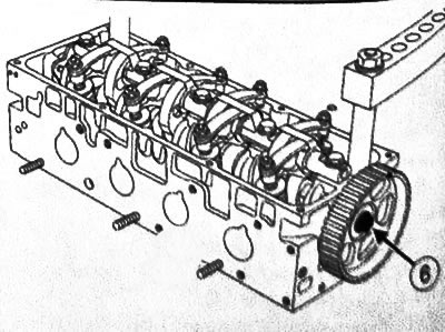
21. Remove the camshaft sprocket.
22. To turn away nuts and bolts of adjustment of a backlash in valves.
23. Loosen the bolts of the rocker shaft and remove it from the cylinder head.
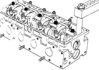
24. Mark the installation position of each rocker arm.
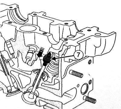
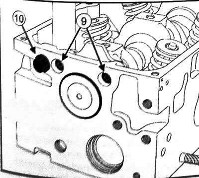
25. Remove the bolts (7) from the camshaft flange.
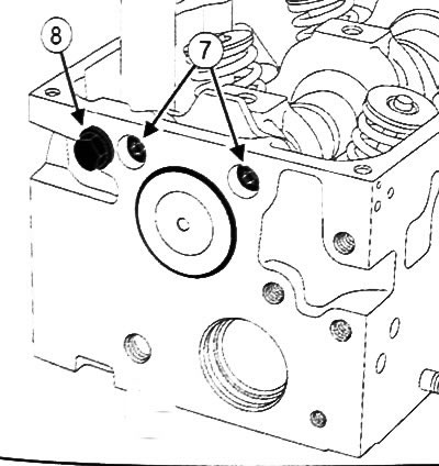
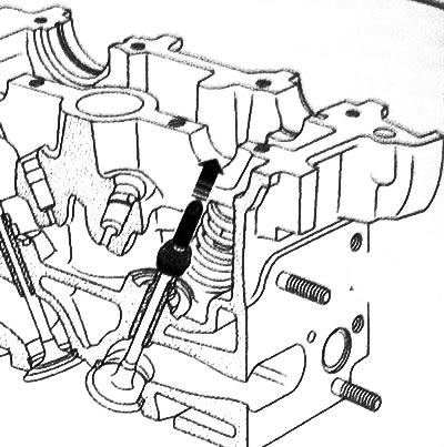
26.Pry off the camshaft end cap with a screwdriver and remove from the cylinder head.
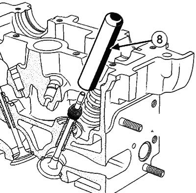
Note: Bolt (8) serves to seal the hole (if available). The bolt must be installed to prevent engine oil leaks.
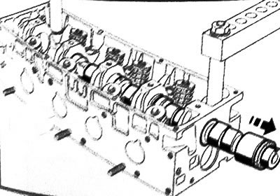
27. To take a camshaft from a head of the block of cylinders.
28.Remove the camshaft seal from the timing drive side.
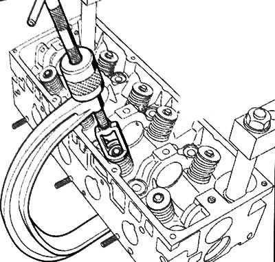
29. Compress the valve spring with a special tool.
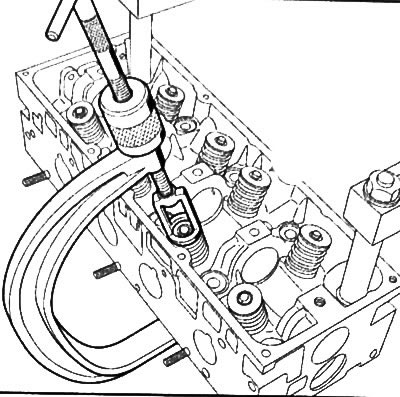
30. Using tweezers, remove the valve cotters and remove the valve disc.
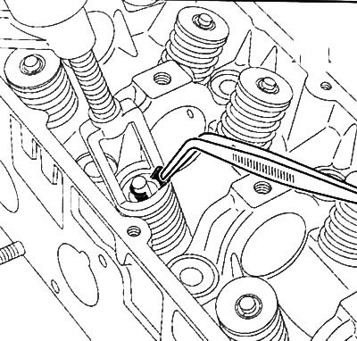
31. Remove the valve spring.
Note: Before removing the valve stem seal, it is important to note the size (H) old valve stem seals on the intake and exhaust sides (the installation size of the caps for inlet and outlet may differ).
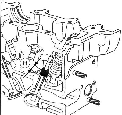
32.Install the valve to mark the installation dimension (H) an old slinger cap with the lower spring retaining washer using a slinger cap installer (Mot. 1511) or a kit for installing oil seals.
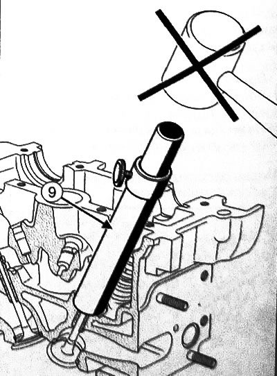
33.Set the mandrel (1) tools for pressing oil seals (Mot. 1511) on the oil cap.
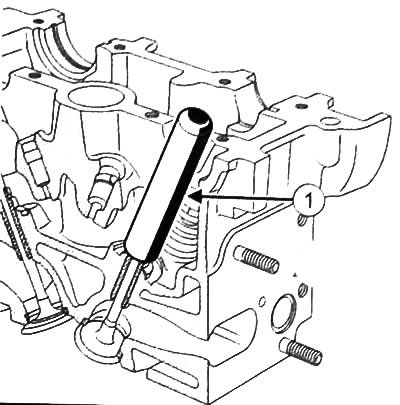
Note: The inner diameter of the mandrel must be identical to the diameter of the valve so that the bottom of the mandrel covers the metal upper section of the valve stem seal.
34.Install the guide tube (2) above the mandrel so that the tube touches the cylinder head.
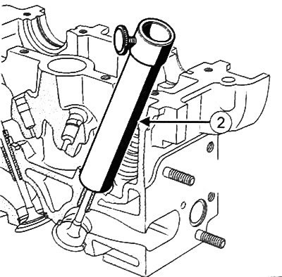
35. Insert sleeve (3) into the guide tube until it contacts the mandrel.
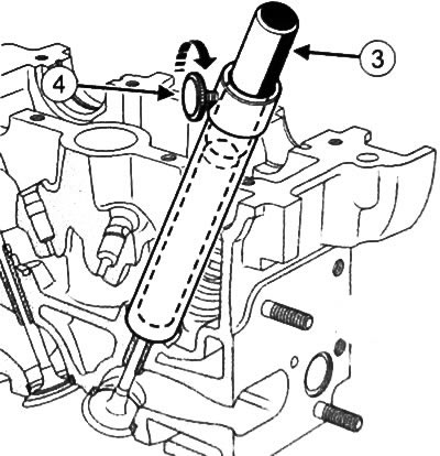
36. Fix the sleeve with the fixing screw (4).
37. Remove the guide tube and bushing assembly, being careful not to loosen the set screw.
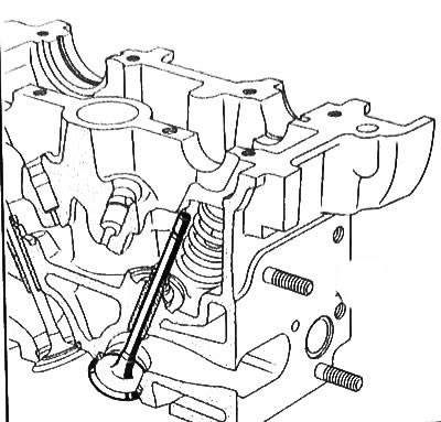
38. Remove the valve.
39. Remove the remaining valves from the cylinder head in the same way.
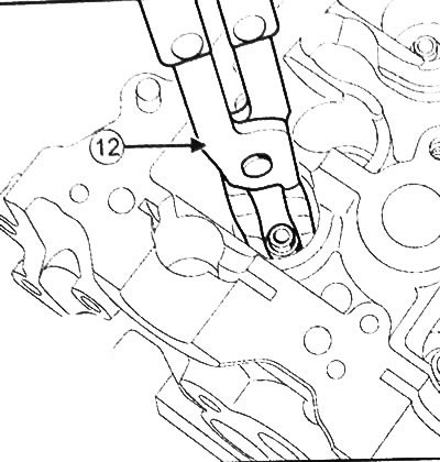
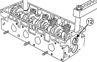
40. With the help of special pliers (Mot. 1335) (12) remove the oil seals from the cylinder head.
41.Remove the lower valve spring seats from the cylinder head.
Assembly
Attention: Be sure to replace the valve stem seals with new ones.
1. Clean the cylinder head, valves, valve springs, valve plates, crackers and valve guides.
2. Install lower valve seats.
Caution: Make sure the valves are seated correctly.
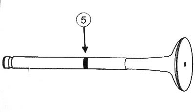
Note: When replacing valves, make sure that the part number of the new valve (5) match the part number of the old one to avoid damage to the valves and their seats.
3. Apply engine oil to the inside of the valve guides.
Note: It is very important to use the slinger cap installer to install the slinger caps (Mol 1611) or a kit for installing oil seals.
4. Insert the valve into the cylinder head.
5. Install the guard (6) (Mot. 1511) on the valve stem.
The inside diameter of the guard must match the diameter of the valve stem.
Attention: Do not lubricate oil seals.
6. While holding the valve against the seat, install the slinger cap (7) onto the guard on the valve stem, and then push the flinger cap through the guard.
7. With the guard removed from the valve stem.
8. Install the mandrel (8) through the valve stem.
Note: The inside diameter of the mandrel must match the diameter of the valve stem. Also, the base of the mandrel should be pressed against the part of the slinger cap that acts as the thrust washer of the valve spring.
9. Press on the slinger cap by gently tapping the mandrel with the palm of your hand until the slinger cap rests against the cylinder head.
10. Repeat the procedure for installing the oil trapping caps for the remaining valves.
11. Install valve springs and valve plates.
12. Compress the valve spring with a special tool, as when removing the valve.
13. Insert breadcrumbs (10) tweezers.
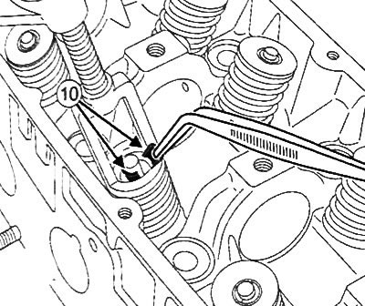
14. Remove the spring compressor from the cylinder head.
15. Install the other valve cotters in the same way.
16. Insert the camshaft from the timing drive side.
17. Install bolts (10) camshaft flange.
18.Tighten the camshaft flange bolts to 10 Nm.
Note: Bolt (10) serves to seal the hole (if available). The bolt must be installed to prevent engine oil leaks.
19. Apply a drop of high-strength fixing compound to the bolt (10) and screw it into the cylinder head.
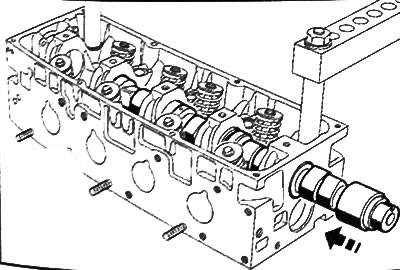
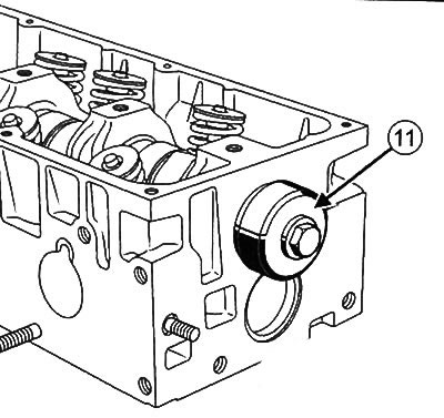
20. Using a mandrel with a diameter of 43 mm (Mot. 1488) (11) Press a new end cap into the cylinder head from the flywheel side.
21. Press in a new camshaft oil seal (see below).
22. Turn the camshaft so that its groove (12) was facing up.
23. Install the axis of the rocker arms with a stamped mark (13) towards the timing gear.
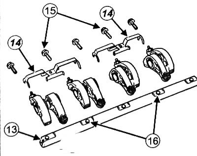
24.Install rocker stops in short sections (14) out.
Note: In some engine versions, the rocker shaft bolts are not the same
25. Place bolts (15) (size M8 «100-28.7mm) in holes (16).
26. Make sure the rocker arm adjusting screws do not touch the valves.
27. Tighten the rocker axle bolts to 23 Nm.
28. Lubricate the threads of the new camshaft sprocket bolt with oil.
29. Install the camshaft sprocket (17).
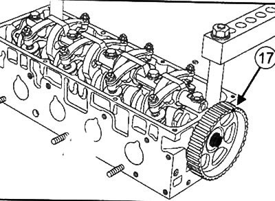
30. Tighten the camshaft pulley bolt to 45 Nm.
31. Install the exhaust manifold.
32. Install the lifting eye on the timing gear drive side.
33. Tighten the lifting eye bolts to 22 Nm.
34. Install the cylinder head water chamber.
35. Install spark plugs.
36. Install the intake manifold.
37. Install the fuel rail.
38. Install throttle valve.
39. Install the coolant temperature sensor and tighten to 33 Nm.
40. Install the wiring mounting bracket.
41. Install the lifting eye on the flywheel side and tighten the M8 mounting bolts to 22 Nm, and M10 to 44Nm.
42. Remove the cylinder head from the stand.
43. Install the cylinder head on the engine.
44. Install rocker cover.
45. Install the timing belt.
46. Install the crankshaft pulley.
47. Install the attachment drive belt.
48. Install the air filter unit.
49. Fill and bleed the engine cooling system.