
A defective cylinder head gasket can be recognized by one or more of the following:
- A) loss of engine power
- b) loss of coolant. Clouds of white exhaust gases when the engine is warm,
- V) loss of oil
- G) coolant getting into the engine oil. In this case, there is not a decrease, but an increase in the oil level. Gray engine oil, foam on dipstick, thin oil,
- and) engine oil getting into the coolant,
- h) the coolant boils strongly,
- And) poor compression in two cylinders located next to each other.
Removing
1. Disconnect the wire terminal «masses» (-) from the battery.
Attention! This deletes data from the memory devices, for example, the security code of the radio. Read the chapter's recommendations «Battery - removal and installation».
2. Remove the toothed belt, see the relevant chapter.
3. Remove the air filter, see relevant chapter.
4. Unscrew bolts of fastening of a cover of a head of the block of cylinders.
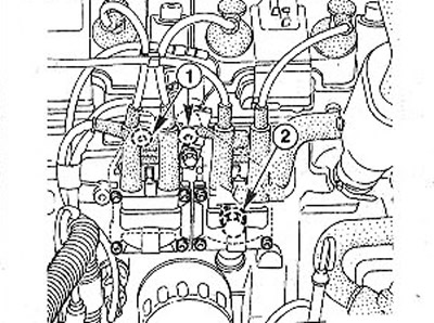
5. 1.4 liter engine (E7J). Disconnect the fuel hoses from the injection system (see arrows in illustration). If the hoses are fixed to the nozzles with crimped clamps, then cut them with side cutters, and when installing the hoses, secure them with clamping clamps. If the fuel hoses are not color-coded, mark them with tape so as not to be confused during installation. When disconnecting the hoses, use a rag to catch any escaping fuel.
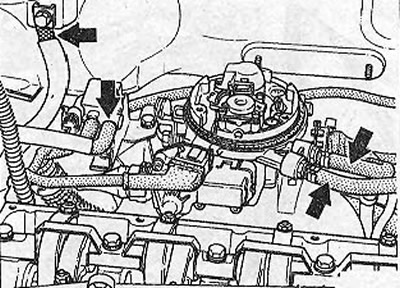
5.5 Disconnect the fuel hoses from the injection system (see arrows)
6. Seal the hose openings with suitable plugs as soon as they are disconnected. For these purposes, you can use clean bolts of a suitable diameter.
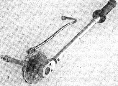
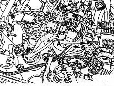
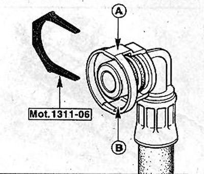
7. All engines, except for those with a volume of 1.4 liters. Loosen the fuel supply line and disconnect it. To do this, press on the side of the clip to lift the clamps A and B. If there is no puller on the clip, use the special tool Mot. 1311-06 by sliding it into the clip from the side and pushing (see illustration).
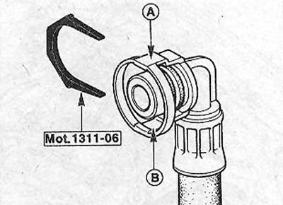
5.7 Use the special tool Mot.1311-06 by inserting it from the side into the clamp and pressing
8. Disconnect the wire «masses» (-), which connects the engine to the body.
9. Disconnect the plug hoses from the canister solenoid valve.
10. 1.4 liter engine (E7J). Disconnect the multi-pin connector of the fuel injection system.
11. Loosen the wire harnesses on the cylinder head and set the wires aside. Before disconnecting, properly mark the places for attaching the wires in order to subsequently lay them in their original places.
12. Unscrew the top bolt of fastening of the rod indicator of level of oil.
13. Disconnect the vacuum brake booster hose from the intake manifold. If the hose is fixed to the branch pipe with a crimped clamp, then cut it with side cutters, and fasten it with a clamp during installation.
14. Disconnect the hose and intake manifold pressure sensor plug. The sensor is screwed to the dividing wall of the engine compartment above the brake fluid reservoir.
15. Disconnect the accelerator cable from the throttle and put it away from the place of work, see the relevant chapter.
16. Drain the coolant, see relevant chapter.
17. Drain the coolant from the cylinder block cooling jacket. To do this, unscrew the plug from the drain hole (see arrow in illustration). Place a container under the hole to collect the liquid. Once draining is complete, screw the plug back in place and tighten to 10 Nm.
5.17 Drain the coolant from the cylinder block cooling jacket. To do this, unscrew the plug from the drain hole (see arrow)
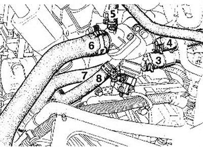
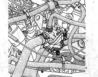
18. Disconnect all hoses 4-7 of the coolant circulation from the thermostat housing (see illustration), opening the clamps with pliers and sliding them onto the hoses. If the hoses are fixed to the nozzles with crimped clamps, then cut them with side cutters, and when installing the hoses, secure them with clamping clamps.
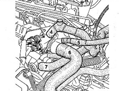
5.18 Disconnect all coolant circulation hoses 4-7 from the thermostat housing
19. Disconnect the temperature sensor plugs on the thermostat housing.
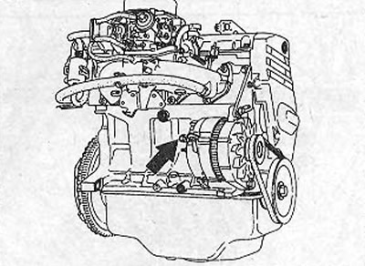
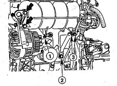
20. Unscrew the top bolt of fastening of the generator (see illustration).
5.20 Remove the upper alternator mounting bolt
21. Remove the mounting bolts and remove the heat-reflecting shield from the exhaust manifold.
22. Disconnect from a final collector a reception pipe of system of release OG.
1.6 liter engine (K7M)
23. Loosen all cylinder head bolts by S turns, working in a cross pattern. After that unscrew all bolts. To do this, you need an E12 head.
24. While lifting the cylinder head. If the head cannot be moved, use a block of wood and tap the head as shown in the illustration (see arrow A).
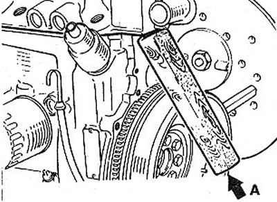
5.24 Use a block of wood and tap the head as shown in the illustration (see arrow A).
1.4 liter engine (E7J)
25. Loosen all cylinder head bolts 1/2 turn, working in a cross pattern. To do this, you need an E12 head.
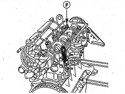
5.25 Do not unscrew bolt F
Attention! Bolt F on the toothed belt side must not be unscrewed (see illustration). There is a centering bushing on this bolt. All other bolts must be completely unscrewed after loosening.
Attention! The cylinder head gasket is usually glued to the head, cylinder block and cylinder liners. For this reason, the cylinder head should not be lifted, because this will remove the cylinder liners and contaminate their seats.
26. Turn the cylinder head to the side around the F bolt or centering sleeve to loosen its fit on the cylinder block. To do this, strike with a rubber mallet in a horizontal direction on the opposite side of the head.
27. Unscrew a bolt E and remove a head of the block of cylinders.
28. Secure the cylinder liners with holders Mot. 588 (see illustration). In the workshop, this operation is performed to prevent them from being skewed when the car is moved or when the engine is cranked. If the car does not move or there is no need to rotate the crankshaft, then the cylinder liners can not be fixed.
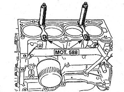
5.28 Secure the cylinder liners with holders Mot. 588
Attention! Lay the removed cylinder head on 2 wooden slats, and not on surfaces mating with the cylinder block. Otherwise, fully open valves may be damaged.
Installation
29. Clean the cylinder head and cylinder block before reassembly with a suitable scraper to remove seal residues. Pay attention to ensure that dirt does not enter the cylinder channels. Plug holes with rags (see illustration).
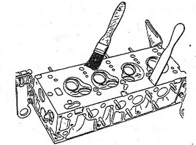
5.29 Clean the cylinder head and cylinder block before reassembly with a suitable scraper to remove any seal residue
Attention! Do not clean the sealing surface of the light alloy cylinder head with a metal scraper. In these cases, it is recommended to use a cleaning agent «Decap-joint», manufactured by RENAULT, which is applied to the surface to be cleaned and left for 10 minutes. After that, the remnants of the sealant are removed with a wooden spatula.
30. 1.4 liter engine (E7J). Remove, if fitted, the cylinder liner holders and check the piston protrusion, see the relevant chapter.
31. Check the cylinder head for distortion (see illustration). Check the curvature with a steel ruler and measuring template at various points on the cylinder head. Permissible deformation must not exceed max. 0.05 mm. Otherwise, replace the cylinder head with a new one. Modification of the cylinder head is not allowed.
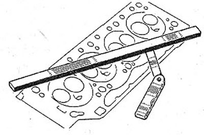
5.31 Check the cylinder head for distortion
32. Check up a condition of a head of the block of cylinders and be convinced of absence of cracks and gouges.
33. Clean the threads of the cylinder head bolt holes on the cylinder block. These holes must be free of oil or other contaminants. If necessary, blow out the holes with compressed air or clean with a screwdriver wrapped in rags that will absorb liquid. Oil can be collected from the holes with a grease gun. If this is not done, then when the fastening bolts are screwed in, excess pressure will be created in the holes, which can lead to a rupture of the cylinder block or an incorrect tightening torque of the bolts.
The cylinder head gasket must be replaced. When laying the gasket, additional use of sealant is not allowed.
34. 1.4 liter engine (E7J). Make sure that the centering sleeve G is in place in the cylinder block (see illustration). Insert sleeve if necessary.
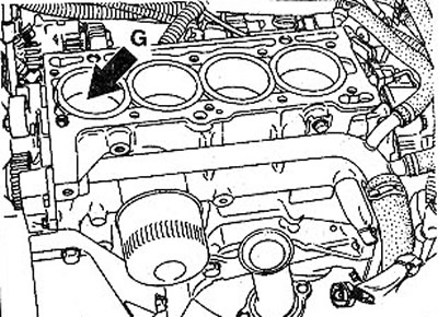
S.34 Check that the centering sleeve G is in place in the cylinder block
35. 1.6 liter engine (K7M). Make sure the dowel sleeves are in place in the cylinder block (see illustration). Insert sleeves if necessary.
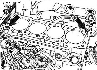
5.35 Check that the centering sleeves are in place in the cylinder block
36. Place a new cylinder head gasket on the cylinder block. The gasket must lie so that not a single hole is blocked.
37. Install the block head on the cylinder block.
38. Be sure to replace the old cylinder head bolts with new ones.
39. Lubricate the threads and contact surfaces of the heads of the cylinder head bolts with a thin layer of clean engine oil.
40. Place washers on the bolts and screw in the bolts by hand.
Attention! The cylinder head bolts are of different lengths. The shortest bolts are screwed in from the side of the intake manifold.
Attention! The cylinder head bolts must be tightened with great care. Before tightening, check the accuracy of the torque wrench. In addition, the tightening sequence of the bolts must be exactly followed.
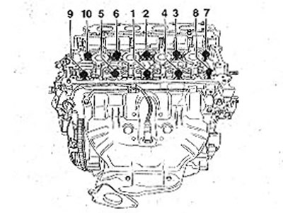
41. Tighten the cylinder head bolts in 9 passes. When performing passes 1 and 2, the bolts are tightened in sequence from 1 to 10 (see illustration).
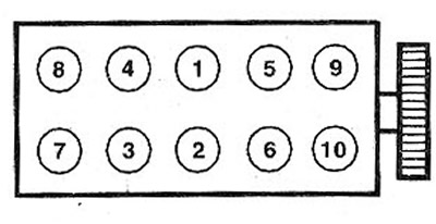
5.41 Tighten the cylinder head bolts in 9 passes. When performing passes 1 and 2, the bolts are tightened in sequence from 1 to 10
5.41 a Torque wrench angle template can be used, e.g. HAZET6690
1.4 liter engine (E7J)
- 1st pass. Tighten the bolts with a torque wrench to 20 Nm.
- 2nd pass. Tighten all bolts by 97°±2°using a standard wrench.
- 3rd pass. Wait at least three minutes for the cylinder head gasket to shrink.
- 4-pass. Loosen bolts 1 and 2. Do not change other bolts.
- 5th pass. Tighten bolts 1 and 2 to 20 Nm, and then tighten by 97°±2°.
- 6th pass. Loosen bolts 3, 4, 5, 6 without changing the tightening of the rest.
- 7th pass. Tighten bolts 3, 4, 5, 6 with a force of 20 Nm, and then tighten them by 97°±2°.
- 8th pass. Loosen bolts 7, 8, 9, 10 without changing the tightening of the rest.
- 9th pass. Tighten bolts 7, 8, 9, 10 with a force of 20 Nm, and then tighten them by 97°±2°.
1.6 liter engine (K7M)
- 1st pass. Tighten the bolts with a torque wrench to 20 Nm.
- 2nd pass. Tighten all bolts with an ordinary wrench by 100°±6°.
- 3rd pass. Wait at least three minutes for the cylinder head gasket to shrink.
- 4-pass. Loosen bolts 1 and 2. Do not change other bolts.
- 5th pass. Tighten bolts 1 and 2 to 20 Nm and then tighten by 110°±6°.
- 6th pass. Loosen bolts 3, 4, 5, 6 without changing the tightening of the rest.
- 7th pass. Tighten bolts 3, 4, 5, 6 with a force of 20 Nm, and then tighten them by 110°±6°.
- 8th pass. Loosen bolts 7, 8, 9, 10 without changing the tightening of the rest.
- 9th pass. Tighten bolts 7, 8, 9, 10 with a force of 20 Nm, and then tighten them by 110°±6°.
Attention! In order to maintain the desired angle of the bolts when they are tightened, it is recommended to put the appropriate marks on the cylinder head. For this purpose, the key is installed on the head of the bolt, and at a distance of 97°a corresponding mark is applied with chalk. You can also cut a 97°goniometer out of cardboard or use an angle template for a torque wrench, e.g. HAZET 6690 (see flashcard 2:41a).
Attention! The cylinder head bolts must not be tightened when the engine is hot.
42. Fix on a final collector a reception pipe of mufflers, the corresponding chapter see.
43. Attach the heat shield to the exhaust manifold.
44. Screw in the top bolt of fastening of the generator.
45. Lay the toothed belt.
46. Connect the plugs of the temperature sensors on the thermostat housing.
47. Connect the cooling system hoses and secure them with clamps.
48. Connect the accelerator cable to the throttle, see the relevant chapter.
49. Connect the plug and hose to the intake manifold pressure sensor.
50. Connect the vacuum brake booster hose to the intake manifold and secure it with a clamp.
51. Screw in the top bolt of fastening of the rod indicator of level of oil.
52. Connect the multi-pin plug of the fuel injection system.
53. Connect the hose and plug to the canister solenoid valve.
54. Fix the wiring harnesses on the cylinder head in their original places, using the labels applied before removal.
55 Connect wire «masses» (-), connecting the engine to the body.
56. 1.4 liter engine (E7J). Connect to branch pipes, being guided by the marks put before removal, fuel hoses and fix them collars. Do not confuse the supply and discharge fuel hoses.
57. All engines except 1.4 liter engine (E7J). Put on fuel hoses and fix them.
58. Install the cylinder head cover.
59. Replace the air filter, see relevant chapter.
60. Fill in the coolant, see the relevant chapter.
61. Check the engine oil level. Add oil if necessary. If the cylinder head was removed due to a head gasket defect, it is recommended, without waiting for the oil change date, to replace it ahead of schedule, along with the oil filter. This is due to the fact that coolant could get into the engine oil.
62. Connect the wire terminal to the battery «masses» (-).
63. Set the clock.
64. Enter, if necessary, the security code into the radio.
Only 113 hp engines.
65. Disconnect wire terminal «masses» (-) from the battery.
Attention! This deletes data from the memory devices, for example, the security code of the radio. Read the chapter's recommendations «Battery - removal and installation».
66. Remove the air filter, see the relevant chapter.
67. Remove the high voltage wire connectors from the spark plugs.
68. Unscrew the bolts of the holders of the ignition coils and remove the coils together with the holders (see illustration).
5.68 Unscrew the bolts of the holders of the ignition coils and remove the coils together with the holders
69. Remove ignition coil covers (see illustration).
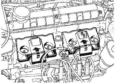
5.69 Remove the covers of the ignition coils
70. Mark electrical wires with adhesive tape and disconnect them from:
- knock sensor,
- ignition timing sensor (determining the TDC of cylinder No. 1),
- intake manifold pressure sensor, and also disconnect the hose from the sensor,
- idle control valve
- intake air and coolant temperature sensor.
- throttle opening angle potentiometer,
- nozzles.
71. Disconnect the crankcase ventilation hose.
72. Disconnect the hose from the canister solenoid valve.
73. Disconnect the vacuum brake booster hose from the intake manifold. If necessary, cut the pressed fastening clamp with side cutters. Subsequently, instead of this clamp, put a clamping one.
74. Disconnect the accelerator cable from the throttle valve and put it away from the place of work, see the relevant chapter.
75. Drain the coolant, see the relevant chapter.
76. Disconnect all coolant circulation hoses from the pipes on the thermostat housing (see numbers 3-8 in the illustration). Unclench the clamps with tongs and shift them onto the hoses. If necessary, cut the pressed fastening clamps with side cutters. Subsequently, instead of these clamps, put clamping ones.
5.76 Disconnect all coolant circulation hoses from the pipes on the thermostat housing (see numbers 3-8)
77. Remove the toothed belt.
78. Remove the roller 10 toothed belt tension (see illustration).
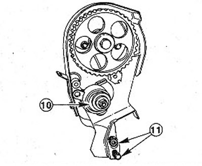
5.78 Remove the pulley 10 toothed belt tension
79. Unscrew the two bolts 11 fastening the rear protective cover of the toothed belt (see illustration 5.78).
80. Unscrew the bolt 12 fastening the coolant hose (see illustration).
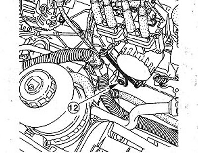
5.80 Unscrew the bolt 12 of the coolant hose
81. Remove the hoist holding the motor. To do this, support the engine from below above the right beam near the oil pump. In workshops, tool Mot. 1159 (see illustration). When using this tool for MEGANE vehicles, the bottom stand must be shortened by about 30 mm to secure the tool as shown in the illustration.
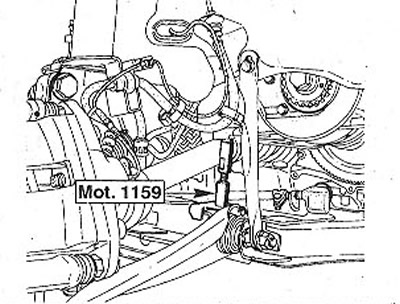
5.81 Tool Mot. 1159 as engine support
82. Support the engine under the water pump. For this purpose, workshops use the loose eye of tool Mot. 1159, which is bolted (see illustration).
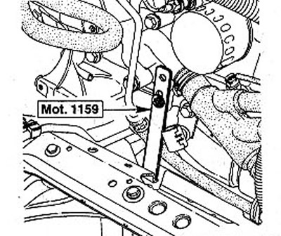
5.82 Support the engine under the water pump. For this purpose, workshops use the loose eye of tool Mot. 1159, which is bolted
83. Make the desired eyelet yourself, using the diagram if it is not in the tool kit (see illustration).

5.83 Make your own eyelet using the diagram if it is not included in the tool kit
84. Remove the throttle valve, see the relevant chapter.
85. Remove the fuel injectors. Make sure that the gaskets do not fall out when removing the injectors 13 (see illustration).
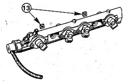
5.85 Make sure that the gaskets do not fall out when removing the injectors 13
86. Loosen all cylinder head bolts 1/2 turn, working in a criss-cross pattern. Then unscrew the bolts completely using a SW 10 socket socket, eg HAZET 986-lOLg.
87. Remove the cylinder head.
Installation
Installation of a head of the block of cylinders is carried out in sequence, return to removal.
88. Screw in and tighten the bolts securing the head to the cylinder block. The bolts are tightened in five passes. When performing passes 1 and 2, the bolts are tightened in sequence from 1 to 10 (see illustration).
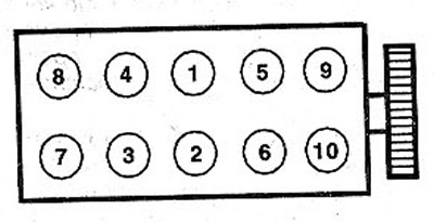
5.88 Screw in and tighten the bolts securing the head to the cylinder block. When performing passes 1 and 2, the bolts are tightened in sequence from 1 to 10
Only 113 hp engines.
- 1st pass. Tighten the bolts with a torque wrench to 30 Nm.
- 2nd pass. Tighten all bolts by 50°± 4°using a standard wrench.
- 3rd pass. Wait at least three minutes for the cylinder head gasket to shrink.
- 4-pass. Loosen bolts 1 and 2 by 180° (1/2 turn). Do not change the tightening of the remaining bolts.
- 5th pass. Tighten bolts 1 and 2 to 25 Nm, and then tighten by 123°±7°.
Repeat the 4th and 5th passes for the bolts 3-4, 5-6, 7-8, 9-10 respectively.
Attention! Tightening the cylinder head bolts on a warm engine is not allowed.
Only 150 hp engines.
For the cylinder head bolts of this engine, a socket head with a T55 hexagon socket is required, for example, HAZET 992 SLg-T55.
89. Screw in and tighten the head-to-cylinder block bolts in four passes in sequence from 1 to 10 (see illustration).
- 1st pass. Tighten the bolts with a torque wrench to 30 Nm.
- 2nd pass. Tighten all bolts with an ordinary wrench by 50°±2°.
- 3rd pass. Wait at least three minutes for the cylinder head gasket to shrink.
- 4-pass. Completely loosen each bolt separately, and then tighten them with a force of 25 Nm, and then tighten them by 107°±2°.
Attention! Tightening the cylinder head bolts on a warm engine is not allowed.
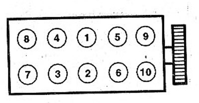
5.89 Screw in and tighten the head bolts to the cylinder block in four passes in sequence from 1 to 10
90. Start the engine and warm it up after driving for some distance. After that, leave the engine to idle until the radiator fan turns on.
91. Stop the engine.
92. Loosen bolts 1, 2, 3 under the intake manifold (see illustration).
5.92 Loosen bolts 1, 2, 3 under the intake manifold
93. Unscrew the two bolts securing the generator / collector (see arrows in illustration 5.92)
94. Allow the engine to cool and tighten the cylinder head bolts in accordance with illustration 2:89 by doing the following:
- 1st pass. Completely loosen bolts 1 and 2. The rest of the bolts remain unchanged.
- 2nd pass. Tighten bolts 1 and 2 to 25 Nm and then tighten by 107°± 2°.
95. Repeat both of these steps for bolts 3-4, 5-6, 7-8, 9-10 respectively.
96. Tighten the bolts under the manifold, as well as the generator mounting bolts.
Diesel engines only
97. Disconnect wire terminal «masses» (-) from the battery.
Attention! This deletes data from the memory devices, for example, the security code of the radio. Read the chapter's recommendations «Battery - removal and installation».
98. Remove the air filter, see relevant chapter.
99. Remove the toothed belt, see the relevant chapter.
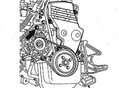
100. Unscrew bolts A of the V-belt tensioner and bolt B, which secures the generator in the upper part (see illustration).
5.100 Unscrew the bolts A of the V-belt tensioner and the bolt B that secures the generator in the upper part
101. Disconnect from a final collector a reception pipe of mufflers, the corresponding chapter see.
102. Disconnect the wire «masses» (-), which connects the engine to the body.
103. Disconnect the fuel return line from the injection pump.
104. Disconnect from a collector the holder of a returnable fuel line.
105. Unscrew the bolts and remove the rear protective cover of the toothed belt (see arrows in illustration).
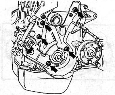
5.105 Unscrew the bolts and remove the rear toothed belt guard (see arrows)
106. Disconnect the oil filter, see the relevant chapter.
107. Disconnect the wires from the generator and set the wiring harness away from the work area.
108. Remove the hoist holding the motor. To do this, support the engine from below near the oil and water pumps.
109. Disconnect all coolant circulation hoses from the nozzles on the thermostat housing (see illustration). Unclench the clamps with tongs and shift them onto the hoses. If necessary, cut the pressed fastening clamps with side cutters. Subsequently, instead of these clamps, put clamping ones.
5.109 Disconnect all coolant circulation hoses from the fittings on the thermostat housing
110. Disconnect the temperature sensor plugs on the thermostat housing.
111. Disconnect the vacuum brake booster hose from the vacuum pump. If the hose is fixed to the pump nozzle with a crimped clamp, then cut it with side cutters, and fasten it with a clamp during installation.
112. Disconnect the accelerator cable from the throttle valve and put it away from the place of work, see the relevant chapter.
113. Disconnect both crankcase ventilation hoses from the oil separator.
114. Disconnect the injection pump power plug.
115. Disconnect the hoses from the solenoid valves.
116. Loosen the fuel supply line on the fuel filter and disconnect it. To do this, press on the side of the clip to lift the clamps A and B. If there is no puller on the clip, use the special tool Mot. 1311 -06 by inserting it from the side into the clamp and pushing (see illustration).
5.116 Use the special tool Mot.1311-06 by inserting it from the side into the clamp and pressing
117. Loosen all cylinder head bolts by S turns, working in a cross pattern. Then unscrew the bolts completely using a T55 hex socket socket, eg HAZET 992-SLg-T55.
118. Loosen the fit of the cylinder head on the block by sliding its lower part.
Attention! The cylinder head cannot be moved aside from the block because it is held by two centering bushes.
119. Remove the head by lifting it up.
Installation
Installation of a head of the block of cylinders is carried out in sequence, return to removal.
120. Select the cylinder head cover gasket of the correct thickness based on the size of the piston protrusion.
Attention! Depending on the protrusion of the pistons, gaskets of three standard sizes are installed. The corresponding size has its own designation in the form of dots on section C on the gasket (see illustration). The number of points can be 0, 2 or 3. When replacing the gasket, install the gasket with the same number of points as the one that was removed. The designation of the cylinder head gasket is visible with the head removed, namely in the front left corner of the engine, when viewed in the direction of travel.
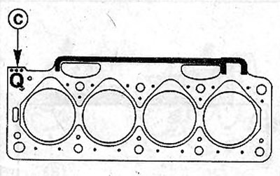
5.120 Select the cylinder head cover gasket of the correct thickness based on the size of the piston protrusion. The corresponding size has its own designation in the form of dots on section C on the gasket
Attention! Pay attention to the fact that when installing the cylinder head, all pistons are at the same height. This means that none of the pistons is at TDC. Otherwise, serious engine damage may result. If necessary, rotate the crankshaft 1/4 turn, and after installing the head, return the shaft to its previous position by unscrewing it back.
If the crankshaft, cylinder block, connecting rods or pistons have been changed, the thickness of the cylinder head gasket to be installed must be re-determined by measuring the protrusion of the pistons.
121. Lay a new cylinder head gasket on the cylinder block. The gasket must lie so that not a single hole is blocked (see arrows in illustration). Make sure the centering bushes A are in place in the cylinder block.
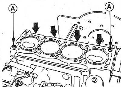
5.121 Lay a new cylinder head gasket on the cylinder block. The gasket must lie so that not a single hole is blocked (see arrows)
122. Tighten the cylinder head bolts in 5 passes. When performing passes 1 and 2, the bolts are tightened in sequence from 1 to 10 (see illustration).
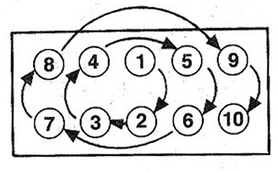
5.122 Tighten the cylinder head bolts in 5 passes. When performing passes 1 and 2, the bolts are tightened in sequence from 1 to 10
1.4-/1.6-litre petrol engines only (K4M/K4J)
Attention! Removal and installation of the cylinder head is possible only with the use of special tools, so this work should be entrusted to a workshop. Below are only the main recommendations and tightening torques for threaded connections.
123. Measure after unscrewing of bolts of fastening of a head of the block of cylinders their length. The maximum allowable bolt length must not exceed 117.7 mm. If at least one of the bolts is longer, then all the bolts must be replaced with new ones. Lubricate the old bolts with a thin layer of oil during their subsequent use. New bolts should not be lubricated.
- 1st pass. Tighten the bolts with a torque wrench to 20 Nm.
- 2nd pass. Tighten all bolts with an ordinary wrench by 240°±6° (see illustration).
Attention! Tightening the cylinder head bolts on a warm engine is not allowed.
5.123 Tighten the cylinder head bolts in two passes
Diesel engines only
- 1st pass. Tighten the bolts with a torque wrench to 30 Nm.
- 2nd pass. Tighten all bolts by 50°±4°with a standard wrench
- 3rd pass. Wait at least three minutes for the cylinder head gasket to shrink.
- 4-pass. Loosen bolts 1 and 2 by 180° (1/2 turn). Do not change the tightening of the remaining bolts.
- 5th pass. Tighten bolts 1 and 2 to 25 Nm, and then tighten by 213°±7°.
Repeat the 4th and 5th passes for the bolts 3-4, 5-6, 7-8, 9-10 respectively.
Attention! Tightening the cylinder head bolts on a turbocharged engine (90 hp) performed after the engine has warmed up.
124. Start the engine and warm it up. Then leave the engine to idle until the radiator fan turns on.
125. Stop the engine and let it cool down to atmospheric temperature.
126. Remove the cylinder head cover and tighten the cylinder head bolts in the sequence from I to 10, tightening them by 120°± 7°.
Attention! For diesel engines with a capacity of 64 hp. and for 98 hp turbocharged diesel engines. tightening the cylinder head bolts on a warm engine is not allowed.