
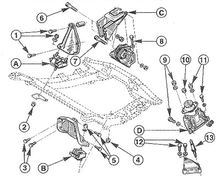
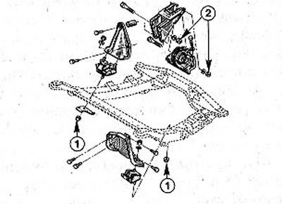
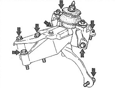
3.0 Suspension of the power unit. Vehicles with 1.4 and 1.6 liter E7J/K7M petrol engines:
A - engine mount. Torques for bolts/nuts:
1 - 40 Nm
2 - 45 Nm
B - mechanical transmission suspension support. Bolt/nut tightening torques:
3 - 40 Nm
4 - 45 Nm
5 - 40 Nm
C - bracket (stabilizing arm). Bolt/nut tightening torques:
6 - 65 Nm
7 - 75 Nm
8 - 55 Nm
D - automatic transmission suspension support. Bolt/nut tightening torques:
9 - 25 Nm
10 - 75 Nm
11 -25 Nm
12 - 40 Nm
13 - 60 Nm
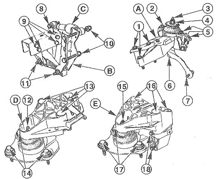
3.0a Suspension of the power unit. Vehicles with 2.0 liter petrol engine and 1.9 liter diesel engine:
A - engine mount. Bolt/nut tightening torques:
1 - 55 Nm. For engines with 16 valves - 40 Nm.
2 - 25 Nm
3 - bolt, 60 Nm
4 - 75 Nm
5 - 25 Nm
6 - nut. 40 Nm
7 - 40 Nm
B - bracket (stabilizing arm). Bolt/nut tightening torques:
8 - 35 Nm
9 - 60 Nm
10 - 65 Nm
11 - 60 Nm
C - shock absorber. Diesel vehicles
D - a support with a shock-absorbing pillow and a torsional vibration limiter. Vehicles with a diesel engine. Bolt/nut tightening torques:
12 - 45 Nm
13 - 40 Nm
14 - 60 Nm
E - a support with a shock-absorbing pillow and a torsional vibration limiter. Vehicles with a 2.0 liter petrol engine. Bolt/nut tightening torques:
15- 45 Nm
16- 40 Nm
17- 60 Nm
18-20 Nm. For engines with 16 valves - 30 Nm
From the engine compartment, the engine is dismantled together with the gearbox by lifting with a hoist or crane. Before dismantling the engine, it is recommended to familiarize yourself with the provisions of the chapter «Gearbox - removal and installation». It is not necessary to disconnect the exhaust and intake manifolds, the fuel injection system, the generator and the starter when dismantling the engine.
Due to the fact that when removing the power plant, you will need to disconnect some nodes in the lower part of the car, you will need four stand goats, as well as a garage jack. Before removing the engine, the fenders should be covered with blankets or a thick cloth to prevent damage.
Depending on the year of manufacture and vehicle equipment, the routing of electrical wiring or hoses, low pressure and cooling system in the engine compartment may differ from those shown in this manual. Due to the fact that it is not possible to give a description for each configuration, each hose or wire must be marked with adhesive tape before disconnecting.
Electrical connection plugs usually have metal clips. In order to unclench them, it is enough to press on their side parts.
The procedure for dismantling the power plant is shown on the example of a car with a body «sedan» with a K7M gasoline engine with a displacement of 1.6 liters.
It is of fundamental importance when removing the engine that all pipelines, hoses and wires are disconnected, the connections of which must be properly marked at the same time so that they can be fixed in place during installation.
Removing
1. Disconnect the ground wire terminal (-) from the battery. Attention! At the same time, some data is deleted from the memory of storage devices, for example, an access code is erased from the radio receiver, which prevents unauthorized use of the receiver. Before disconnecting the battery, read the instructions in chapter «Removing and installing the battery».
2. Remove the hood, see the relevant chapter.
3. Mark with paint the position of the front wheels relative to the hub. This will allow you to later set the balanced wheel to its original position.
4. Loosen the wheel bolts. In this case, the wheels of the car must be on the ground.
5. Install the front of the car on the goats and remove the wheels.
6. Remove the engine mudguard, if installed.
7. Drain the gearbox oil, see relevant chapter.
8. Drain the coolant, see relevant chapter.
Left side of the car
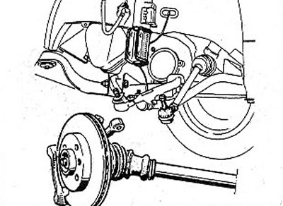
9. Remove the caliper from the brake disc of the left front wheel and secure it with wire to the suspension strut (see illustration).
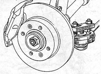
3.9 Remove the caliper from the brake disc of the left front wheel and secure it with wire to the suspension strut
10. Vypressuyte the left tip of cross steering draft from an aperture on a rotary fist, the corresponding chapter see.
11. Unscrew three bolts of fastening of the left power shaft to a transmission.
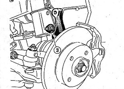
12. Unscrew the nut 2 and remove the clamping bolt of the ball joint (see illustration).
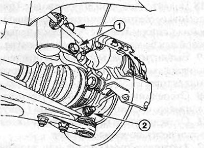
3.12 Unscrew nut 2 and remove the ball joint clamping bolt
13. Disconnect the transverse lever from the steering knuckle by pushing it down. If the ball joint pin sits tightly and does not come out of the hole, it can be released using a pry bar, which should be inserted between the bottom and the lever.
14. Unscrew the two bolts 1 that secure the lower part of the suspension strut to the hub (see illustration 3.12).
15. Give a rotary fist outside. In this case, the drive shaft will come out of the gearbox (see illustration).
3.15 Move the steering knuckle out
Attention! Do not subject the drive shaft to a significant angle of inclination and do not damage the anthers of the CV joints.
Right side of the car
16. Drive out the expansion pin with a suitable punch (diameter 3 mm) from the right drive shaft (see illustration).
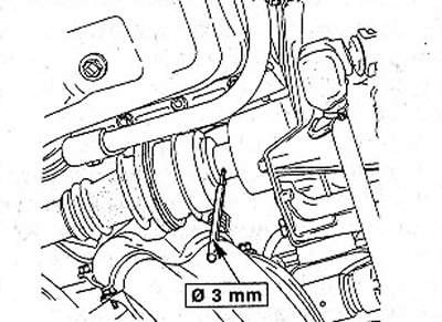
3.16 Drive the spacer pin out of the right drive shaft with a suitable punch
17. Unscrew a nut and take the top bolt by which the lower part of an amortization rack is fixed. Do not unscrew the nut of the lower bolt 3, but only loosen its tightening (see illustration).
3.17. Do not unscrew the nut of the lower bolt 3, but only loosen its tightening
18. Give a rotary fist outside. At the same time, the water shaft will separate from the gearbox, which should be fixed with wire or twine behind the steering mechanism.
19. Unscrew bolts and disconnect a heat-reflecting guard of a final collector.
20. Disconnect a reception pipe and the catalyst, the corresponding chapter see.
21. Disconnect the shift fork rod from the gearbox.
22. Attach the ropes of the crane or hoist to the eyes of the engine and slightly raise it (see illustration).
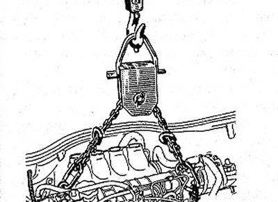
3.22 Attach the ropes of the crane or hoist to the engine lugs and raise it slightly
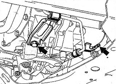
23. Unscrew the nuts 1 fastening the engine support and gearbox (see illustration).
3.23 Unscrew the nuts 1 fastening the engine support and gearbox
24. Unscrew nuts 2 racks of the anti-roll bar (see illustration 3.23).
25. Remove the power steering pipe bracket bolt (see illustration).
3.25 Remove the bolt securing the power steering pipe bracket
26. Disconnect from the gearbox, if any, the speedometer drive shaft.
27. Disconnect the reversing light switch plug on the gearbox.
28. Remove the air filter, see relevant chapter.
29. Disconnect the accelerator cable from the throttle valve and put it away from the place of work, see the relevant chapter.
30. Disconnect the clutch cable from the gearbox, see the relevant chapter.
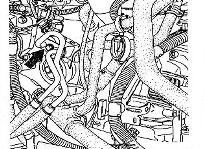
31. Disconnect the coolant circulation hoses 4,5,6,7,8 (see illustration). To do this, release the clamps and slide them onto the hoses. Clamp clamps can be compressed with a gas wrench or use a special HAZET 798-12 wrench.
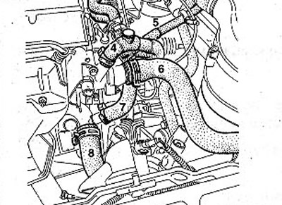
3.31 Disconnect the coolant circulation hoses 4, 5, 6, 7, 8
32. Unscrew bolts of fastening of a broad tank for a cooling liquid and, without disconnecting hoses from it, fix a tank on a body.
33. Disconnect the vacuum brake booster hose from the intake manifold by cutting the clamping collar with side cutters. During installation, instead of a clamping collar, a tightening one should be installed.
32. Vehicles with 1.4 liter E7J engine. Remove the radiator.
33. Vehicles with 1.4 liter E7J engine. Remove the ignition block, see the relevant chapter.
34. Disconnect the hose and plug from the pressure sensor in the intake manifold. The sensor is mounted on a partition above the brake fluid reservoir.
35. Vehicles with 1.4 liter E7.J engine. Label all fuel lines with tape to later secure them in their original places.
36. Disconnect the supply and return fuel hoses by opening the clamping clamps (see illustration). Before disconnecting the hoses, place a rag to collect the escaping fuel. Immediately after disconnecting, plug the hoses with suitable plugs or clean bolts of a suitable diameter.
3.36 Disconnect the supply and return fuel hoses by opening the clamping clamps
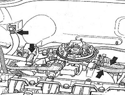
37. All vehicles except vehicles with 1.4 liter E7J engine. Disconnect the fuel supply line. To do this, press the clip, which releases the retaining tabs A and B. If there is no pull-out tool on the clip, fit special tool Mot. 1311 -06 and push it down (see illustration).
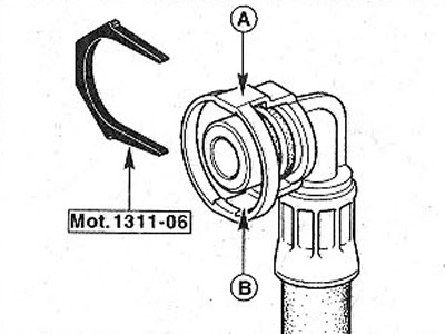
3.37 Disconnect the fuel supply line by opening the retaining clip
38. Disconnect the wire «masses» (-), which connects the engine to the body.
39. Disconnect the canister solenoid valve hose.
40. Disconnect the plug of the power steering and air conditioning pushbutton switch. The switch is located under the power steering reservoir near the lower transverse arm.
41. Disconnect the radiator fan connector.
42. Disconnect the thermal switch plug on the radiator.
43. Remove the relay box in the engine compartment by pushing it up (see illustration).
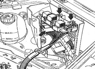
3.43 Remove the relay box in the engine compartment by pushing it up
44. Disconnect the relay plugs.
45. Unscrew bolts of fastening of an arm of the block of management of the engine and fix the block together with an arm with a wire on the engine.
46. Disconnect the power wires from the starter terminals.
47. Release the injection power wire attached to the drain box (see illustration).
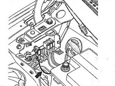
3.47 Release the injection system power wire attached to the drain box
48. Remove the V-belt / V-ribbed belt, see the relevant chapter.
49. Remove the belt pulley from the power steering pump, see the relevant chapter
50. Unscrew the bolts I and 2 fastening the power steering pump and the air conditioning compressor and fix the removed mechanisms on the body (see illustration).
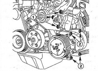
3.50 Unscrew the bolts 1 and 2 fastening the power steering pump and the air conditioning compressor and fix the removed mechanisms on the body
Attention! Do not open the power steering system and the air conditioning refrigerant circulation system. Skin contact with refrigerant can cause frostbite!
51. Attach the A/C low pressure hose to the air filter bracket.
52. Slightly raise the engine so that you can unscrew and remove the three bolts of the stabilizer bar strut, as well as the gearbox mounts.
53. Carefully lift the power unit up, while leading it with your hand so as not to damage the body.
Installation
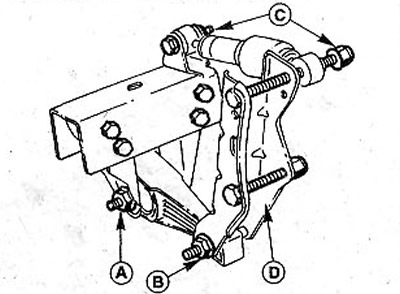
54. Check the condition of the engine mounts, coolant hoses, as well as oil and fuel lines and make sure they have not become porous or cracked. If necessary, replace the corresponding part with a new one.
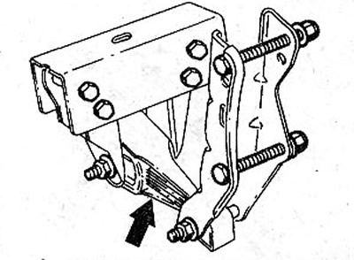
55. Check, if the gearbox was disconnected from the engine, the thickness of the friction lining of the clutch disc. If the lining has significant wear or the car has a high mileage, then the clutch should be completely replaced. If there is noise from the release bearing when pressing the clutch pedal, replace the bearing.
56. Clean the release bearing and input shaft splines, and then lubricate them with MoS2 molybdenum grease.
57. Make sure that both alignment pins, which ensure the correct connection of the engine and gearbox, are in their mounting holes. If they are missing, fit the fitting sleeves, see the relevant chapter.
58. Tighten the engine and gearbox mounting bolts. In this case, the MIO bolts are tightened with a force of 45 Nm, and the M12 bolts - 55 Nm.
59. Carefully slide the assembled power pack into the engine compartment. When lowering the block onto the supports, be careful not to damage the body.
60. Tighten the nuts of the engine and gearbox mounts. At this stage, do not perform their final tightening.
61. Make sure that the power block is on supports without tension. To do this, before tightening the bolts and nuts, feed the block from side to side. Tighten the bolts and nuts with the application of the prescribed torques indicated in the legend to the illustration «Engine and gearbox mount».
62. Fasten the anti-roll bar to the gearbox with a force of 65 Nm, and on the carrier frame - 75 Nm.
63. Tighten the gearbox mount nuts to 45 Nm.
64. Release the air conditioner compressor low pressure hose from the air filter mount.
65. Reinstall and secure the power steering pump and A/C compressor.
66. Install a belt pulley on the power steering pump shaft, see the relevant chapter.
67. Put on the V-belt/V-ribbed belt, see the relevant chapter.
68. Fasten the injection system power wire to the clamp on the drain box.
69. Connect the wires to the starter terminals, see the appropriate chapter.
70. Reinstall the engine control unit, see relevant chapter.
71. Connect the hose to the canister solenoid valve.
72. Connect the multi-pin plug of the fuse block in the engine compartment.
73. Fasten the relay box in the engine compartment.
74. Cars with a 1.4-liter engine. Install the radiator, see relevant chapter.
75. Cars with a 1.4-liter engine. Install the ignition module, see relevant chapter.
76. Connect the thermoswitch plug.
77. Connect the radiator fan connector.
78. Connect the plug of the pressure switch of the power steering and air conditioning.
79. Connect the wire «masses» (-) between engine and body.
80. Connect the plug and put the hose on the pressure sensor in the intake manifold.
81. Connect the vacuum brake booster hose to the intake manifold and secure it with a clamp.
82. Cars with a 1.4 liter engine (E7J). Connect the fuel lines, following the markings made before disconnecting them, and secure with clamps. Do not confuse the supply and return fuel hoses.
83. Cars with a 1.4-liter engine. Put on fuel hoses and fix with clamping collars.
84. Reinstall and secure the coolant expansion tank.
85. Connect the coolant hoses and secure them with clamps.
86. Fasten the clutch cable to the gearbox, see the relevant chapter.
87. Fasten the accelerator cable to the throttle, see the relevant chapter.
88. Replace the air filter, see relevant chapter.
89. Connect the reversing light switch plug.
90. Fasten, if available, the speedometer drive cable to the gearbox.
91. Screw the power steering pipe bracket.
92. Reinstall the shift fork rod on the gearbox, see illustration.
93. Connect to a final collector a reception pipe and the catalyst, the corresponding chapter see.
94. Replace the heat shield in front of the exhaust manifold.
95. Install the right and left drive shafts.
96. Fix the lower part of the spring strut to the steering knuckle by tightening the bolts to 170 Nm.
97. Establish tips of cross steering draughts, the corresponding chapter see.
98. Establish a spherical joint of a rotary fist, the corresponding chapter see.
99. Reinstall the front brake calipers.
100. Fill the system with coolant and remove air from it, see the relevant chapter.
101. Fill the gearbox with oil, see the relevant chapter.
102. Check the engine oil level and top up if necessary, see relevant chapter.
103. Reinstall, if equipped, the engine mudguard.
104. Establish forward wheels according to the marks put at removal. Before doing this, lubricate the centering saddle of the rim on the hub, as well as the cone of the wheel bolts with a thin layer of bearing grease. Do not lubricate the threads of the wheel bolts.
105. Screw in wheel bolts and lower the car.
106. Tighten the wheel bolts in a criss-cross pattern to 90 Nm.
107. Replace the hood, see the relevant chapter.
108. Connect to the negative pole of the battery wire terminal «masses» (-).
110. Set the clock.
111. Enter, if necessary, the security code into the radio.
Vehicles with 113 hp. F3R engine
112. Remove wheel arch liners from the right and left wings, the corresponding chapter see. n3Remove the protective cover covering the engine mount cushion.
114. Remove the engine control unit bracket.
115. Remove the clips that secure the air conditioning low pressure hose to the gearbox mount.
116. Unscrew the nuts and remove the stabilizer mounting bolts (see illustration).
3.116 Unscrew the nuts and remove the stabilizer mounting bolts
Diesel vehicles
117. Remove wheel arch liners from the right and left wings, the corresponding chapter see.
118. Disconnect the plugs and hoses of the solenoid valves for increasing the idle speed and the exhaust gas recirculation system.
119. Disconnect the altimeter.
120. Loosen the hose on the fuel filter and disconnect the hose.
121. Disconnect the fuel return hose from the high pressure fuel pump to the fuel filter.
122. Remove the battery retaining clip.
123. Disconnect the oil cooler hoses from the radiator. Plug the hose openings with suitable plugs and put the hoses away from the work area (see illustration).
3.123 Disconnect the oil cooler hoses from the radiator
124. Loosen nut A. Do not unscrew the nut itself (see illustration).
3.124 Loosen nut A
125. Unscrew the nut B and remove the bolt (see illustration 3.124).
126. Unscrew the nuts C, remove the bolts and remove the shock absorber (see illustration 3.124).
127. Unscrew the nuts and remove the bracket D of the rear suspension of the gearbox (see illustration 3.124).
128. Remove the cover that covers the support plate of the front right shock absorber of the engine mount (see illustration).
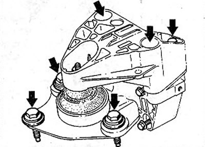
3.128 Remove the cover that covers the support plate of the front right shock absorber of the engine mount
129. Remove the torsional vibration limiter from the front right engine mount.
Attention! After installation, the vibration limiter must be adjusted using using the special tool RENAULT Mot.1289-03.
130. Disconnect the gearbox suspension bracket (see illustration).
3.130 Disconnect the gearbox suspension bracket
Vibration limiter adjustment (1.9 liter diesel and 2.0 liter petrol vehicles)
131. Loosen both bolts E that secure the stopper to the base plate and insert tool Mot. 1289-03 (see illustration).
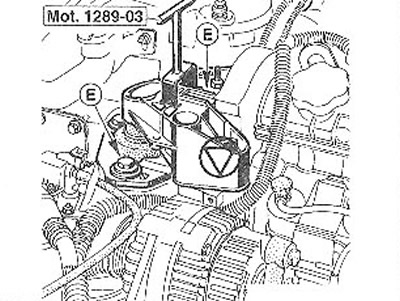
3.131 Loosen both bolts E that secure the stopper to the base plate and insert tool Mot.128S-03 into the holes on the plate. The illustration shows a gasoline engine
132. Tighten bolts E to 60 Nm without removing the special tool.