



Preparation
The C-type engine can be removed from the engine compartment without the gearbox. The F-type engine, on the contrary, must be removed with the gearbox. The necessary device for this is a lifting block fixed in the roof of the garage, on which it is necessary to fix the crossbar, on which the engine will be hung on chains. In addition, use a mobile jack and jack stands to lift and secure the Renault 19. When disassembling and assembling the engine, you will need an assistant. Before starting work, carefully study the imageengine, in order to know where and how the engine components and elements are located in the engine compartment.
The Renault 19 engine, regardless of its type, contains a large number of electrical wires and vacuum pipes. Therefore, you must first mark all connections and pipes so as not to mix them up when assembling the engine. A detailed description of the disassembly process of individual elements can be found in the corresponding chapters devoted to the examination of these units.
The figure shows the engine balance mount, on which the diesel engine is elastically attached. When removing the engine, be sure to apply cross marks to all attachment points to the body to correctly install the engine in place.
Elements of the right suspension
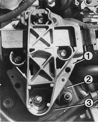
1 - engine suspension arm; 2 - vibration limiter; 3 - fastening of the hydroelastic engine bearing.
Gearbox suspension components
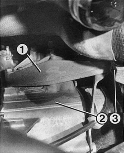
1 - gearbox support; 2 - gearbox; 3 - body side member.
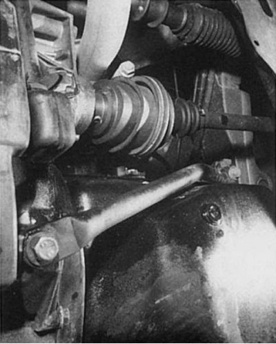
The picture shows a spacer between the engine and the gearbox. It gives the engine-gearbox connection additional rigidity.
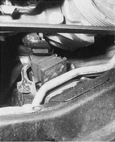
Depending on the engine type, its suspension is designed differently. It is very important to check its technical condition and tighten the bolts with the prescribed torque.
Disassembly
1. Disconnect the battery cable from the terminal and remove the battery.
2. For safety, remove the hood.
3. Remove the air filter and air duct hoses.
4. Drain the oil from the engine.
5. Drain the coolant into a clean container. To do this, remove the lower hose from the radiator pipe.
6. Disconnect the interior heating hoses from the front wall of the body.
7. Remove the radiator and radiator fan.
8. On a vehicle with a gasoline engine, disconnect the gas rod from the throttle shaft lever; on a diesel engine, disconnect the gas rod from the high-pressure fuel pump.
9. Disconnect all electrical wires: coolant temperature sensor, oil pressure switch, oil level sensor, knock sensor, engine cooling fan thermostat or fuel injection temperature sensor, ignition coil (gasoline engine car), glow plugs (diesel), throttle potentiometer (gasoline engine car), engine switch and cold start device, high-pressure fuel pump (diesel), starter wire, rear light switch and engine or gearbox ground wire.
10. Disconnect the fuel hoses: for single-point injection, the fuel supply and recirculation hoses from the injection device, for multi-point injection, from the fuel supply distributor and recirculation from the pressure regulator. On a diesel engine, remove the fuel filter with the mount and secure it vertically on the engine.
11. Plug the fuel hoses to prevent dirt from entering and tie them with wire if necessary.
12. Type "F" engines: disconnect the ATF supply hose clamps (automatic transmission fluids) and the reservoir of the hydraulic drive of the steering gear.
13. Drain the ATF from the tank and remove the hoses from it.
14. Turbocharged diesel engine. Remove the turbocharger radiator air pipes.
15. Remove the alternator V-belt.
16. Remove the steering gear hydraulic pump from the engine housing and tie it to the front crossmember.
17. Type "F" engines: remove the connecting spacer between the engine and gearbox and drain the oil from it into a clean container.
18. Disconnect the lambda probe connectors.
19. Disconnect the exhaust pipe and remove it.
20. Engine type "C": disconnect the coolant pump hoses.
21. Remove the V-belt.
22. Disconnect the brake booster hose from the engine.
23. Remove the metal flywheel cover.
24. Turn the crankshaft V-belt pulley until the bushing key is at the top.
25. Loosen the crankshaft pulley and remove it together with the bushing. To prevent the crankshaft from moving, engage 4th gear and ask an assistant to press the brake pedal or secure the engine with a screwdriver inserted into the flywheel ring gear.
26. Unscrew the rear starter mount.
27. Disconnect the electronic ignition system sensors.
28. Unscrew the connecting bolts of the gearbox and engine.
29. Unscrew the two centering pins on the left and right of the engine or gearbox.
30. Unscrew the lower nut securing the right (in the direction of movement) engine bearing.
31. Secure the hook of the lifting device to the engine eye.
32. Secure the gearbox with a car jack to prevent it from falling.
33. Use a crowbar or a powerful screwdriver to pry the engine away from the gearbox.
34. Begin to lift the engine slowly and carefully from the engine compartment, being careful not to damage the right drive shaft when separating the engine from the gearbox.
35. Type "F" engines: remove the speedometer drive from the gearbox. To do this, squeeze the safety clips.
36. Disconnect the clutch rod from the gearbox.
37. If a transverse rod is installed between the shock absorber struts, remove it.
38. Pull back the gearshift device sleeve and remove the control rod.
39. Tie the control rod and the exhaust pipe with wire.
40. Diesel: remove the oil cooler and secure it to the engine.
41. Remove the preheating control unit and tie it to the engine.
42. Type "F" engines: remove the front wheels.
43. On the left side of the car, remove the brake clamp and tie it with wire to the wing so that the brake hose is not stretched or twisted.
44. Disconnect the steering rod from the steering knuckle arm.
45. Remove the drive shaft joint from the gearbox (3 bolts).
46. Disconnect the lower shock absorber mount from the steering knuckle.
47. To avoid excessive load on the joints, tie the drive shaft to the steering with wire. The bending angle of the joints should not be too large. Try not to damage the sealing cuffs of the drive joints.
48. Disconnect the drive shaft spacer pin from the gearbox using a punch.
49. Disconnect the lower shock absorber mount from the steering knuckle (2 bolts with nuts).
50. Disconnect the ball joint of the transverse control arm from the steering knuckle (one bolt with a nut).
51. Tilt the steering knuckles outward until the drive shaft comes out of the gearbox. Do not bend the drive shaft joints too much.
52. Secure the engine to the lift and lift it until the cables (chains) are slightly taut.
53. Remove the engine and gearbox mounts by unscrewing the mounting bolts.
54. Diesel: disconnect the engine balance mount (right side) from the body.
55. Remove the gearbox mount.
56. Next, unscrew the bolt, remember the sequence of installing the torque damping bracket, and remove it from the gearbox.
57. Carefully lift the engine with the gearbox so as not to damage anything.
Engine installation
When installing the engine, it is necessary to replace all self-locking nuts with new ones, since a poorly secured engine or gearbox mount will impair the vehicle's performance and may cause serious damage. The engine is installed in the reverse order of removal.
1. Lower the engine or engine and transmission into the engine compartment, being careful to avoid damage.
2. Engine type "C": align the clutch with the splines of the gearbox input shaft.
3. Connect the engine by inserting the centering bolts to the gearbox with the mounting bolts and screw it on.
4. Install the engine in its normal position and tighten the bolts to a torque of 45 Nm.
5. Engine type "F": adjust the front and rear engine mounts and tighten the bolts (40 Nm)
6. Diesel: install the right balance suspension. Tighten the nut to a torque of 45 Nm.
7. Install the gearbox mount and tighten the bolts to a torque of 45 Nm.
8. Install the torque damping bracket and tighten the nut on the bracket pin to a torque of 65 Nm.
9. Engine type "F": after all fasteners have been tightened to the required torque (see table below), remove the engine and gearbox from the hoist hook.
10. Install the remaining elements in the reverse order of removal.
11. Start the engine and check for oil leaks. Check the cooling system in the same way.
12. When the engine reaches operating temperature, check the ignition timing and idle speed. Adjust if necessary.
Tightening torques
details | 1.4-liter engine (C3J), Nm | 1.7-/1.8-liter/ 16-valve engine (F3N / F3P / F7P), Nm | Diesel (F8Q), Nm |
| Engine mount | 40 | 40—50 | — |
| Left suspension nuts | — | — | 25 |
| Left balance suspension | — | — | 45 |
| Right balance suspension | — | — | 45 |
| Gearbox mounting rubber support bolts | — | — | 45 |
| Oil pan | Control data | 12—15 | 12—15 |
| Timing Belt Tensioner | — | 50 | 50 |
| Crankshaft pulley | * | 90—100 | 90—100 |
| Timing Belt Pulley for Camshaft | — | 50 | 50 |
| Crankshaft chain sprocket | 30 | — | — |
| Axle system with valve levers | 15—20 | — | — |
* 80 Nm (bolt 40 mm); 110 Nm (bolt 45 mm)