
Elements of the valve timing mechanism on a 1.8-liter engine
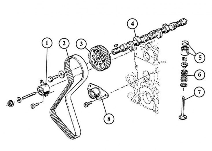
1 - tension roller of the toothed belt; 2 - toothed drive belt; 3 - a pulley of a gear belt of a drive of a camshaft; 4 - camshaft; 5 - a glass pusher with an adjusting washer; 6 - valve spring with small parts (e.g. valve stem gasket); 7 - valve; 8 - toothed belt guide roller.
Elements of the diesel gas distribution mechanism
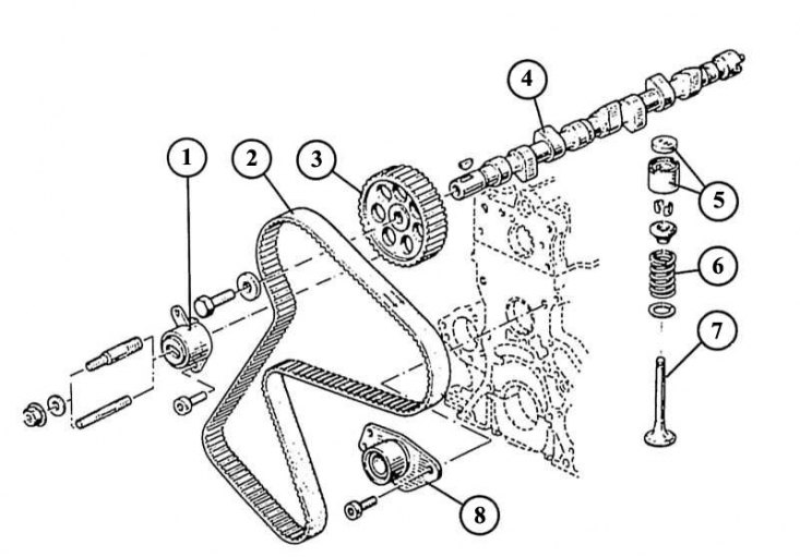
1 - tension roller of the toothed drive belt; 2 - toothed drive belt; 3 - an asterisk of a gear belt of a camshaft; 4 - camshaft; 5 - a glass pusher with an adjusting washer; 6 - valve spring with composite parts; 7 - valve; 8 - guide roller of the toothed drive belt.
16V engine valve timing mechanism
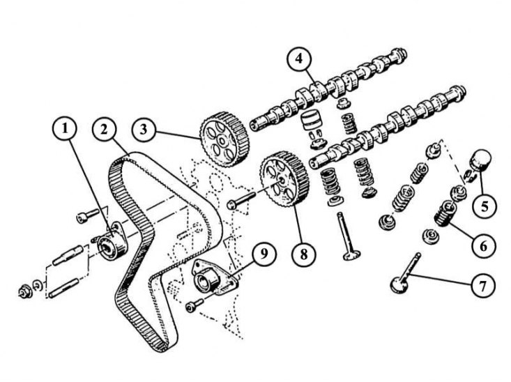
1 - tension roller of the toothed belt; 2 - toothed drive belt; 3 - an asterisk of a gear belt of a final camshaft; 4 - final camshaft; 6 - double valve spring with components; 7 - valve; 8 - an asterisk of a gear belt of an inlet camshaft; 9 - toothed belt guide roller.
You must have at least one assistant to carry out repair and maintenance work on the cylinder head. For the work described below, you need to have a torque wrench (wrench with torque gauge).
Camshaft disassembly
Type motors «F», except 16-valve
If the camshaft is removed on an unremoved cylinder head, then the removal of the toothed belt is added to the work carried out. In addition, for a diesel engine, it is necessary to adjust the injection moment of the high-pressure fuel pump again. On the 16-valve engine, work is carried out in the same way, but with a larger volume and degree of complexity compared to the F-engine, so the 16-valve engine is best repaired in an auto repair shop.
1. Fix the camshaft timing belt pulley with a No. 10 socket wrench or a screwdriver inserted into one of the pulley holes.
2. Turn off the central bolt of fastening of a pulley of a camshaft.
3. With light blows of a plastic hammer, separate the toothed belt pulley from the cone-shaped camshaft seat.
4. Remove the camshaft spring washer.
5. Remove the ignition distributor (for petrol engines) or, respectively, the brake booster vacuum pump (for diesel).
6. Number the camshaft bearing caps by punching or chalk (for later assembly).
7. Remove bearing caps 1, 3 and 5.
8. Unscrew the nuts of the bearing caps 2 and 4 alternately crosswise.
9. Remove the camshaft from the cylinder head.
10. When you remove the valve lifters, mark them along with their related shims (you must also record the dimensions of the shims). This is very important for the subsequent assembly!
11. Lubricate work surfaces before assembly.
12. Install the camshaft so that the cams of cylinder No. 1 look symmetrically up.
13. Establish covers of bearings according to the sequence noted at dismantling. Tighten the 6 mm bolts to 10 Nm and the 8 mm bolts to 20 Nm.
14. Install the camshaft timing belt sprocket - do not forget to install the segment key and tighten the central bolt with a torque of 50 Nm.
15. Further work is carried out in the reverse order of the disassembly process.
16. Check up a backlash in the valvate mechanism and if necessary adjust it.
Note. Recommendation: Apply sealant to the darker areas of bearing caps 1 and 5 (For example, «Kuril» (Curil)).
Make sure that the running surfaces of the camshaft bearings and bearing caps are not damaged.
Hydraulic lifters 16-valve engine
Valve knock
Valve knocking in a 16-valve engine indicates a malfunction of one or more hydraulic lifters. Valve knocking may also occur in properly working hydraulic lifters if:
- after starting the engine, oil does not immediately enter the hydraulic compensator;
- the engine worked for a long time at high speeds at high ambient temperatures, and the engine oil became liquid;
- The machine has not been used for a long time. After the engine warms up, the knocking should stop.
Determining the malfunction of hydraulic lifters
- start the engine and let it run until the electric fan of the engine cooling system turns on;
- increase the speed to 2000 rpm;
- if the knocking of the valves does not stop, then turn off the engine and remove the cylinder head cover;
- install the 1st cylinder (as when adjusting the gap in the valve mechanism) to the TDC position. The camshaft cams should look up left and right;
- press the hydraulic compensator to be checked with a wooden rod. If more than 0.1 mm is pressed through, then it must be replaced.
Dismantling of a head of the block of cylinders
1. All engines: disconnect the wire «masses» from the battery terminal.
2. Remove the air filter.
3. Drain the coolant into a clean container, see chapter Cooling system.
4. Drain the engine oil.
5. Disconnect the electrical wires from the terminals and mark them for reassembly.
6. Disconnect the front exhaust pipe from the muffler exhaust manifold and from the main muffler.
7. Petrol engines: Disconnect the fuel hoses from the injection system and plug them. Be careful! The power system is under pressure.
8. Remove the brake vacuum hose from the intake manifold. At the next assembly, replace the crimp collar on the hose.
9. Diesel: Disconnect the fuel recirculation hoses going to the high pressure fuel pump from the injectors.
10. Disconnect the fuel lines from the high pressure fuel pump and injectors and fold them over a clean piece of cloth.
11. Plug the holes of the high pressure fuel pump and injectors with small plugs made of soft material.
12. Remove the brake booster vacuum pump.
13. Remove filter with heater. Disconnect the heated air supply hoses with the bracket from the engine.
14. Disconnect the wire «masses» engine.
15. Turn off the bottom bolts of a casing of the generator.
16. Turbocharged Diesel: Disconnect the lines to the radiator and charge cooler.
17. Remove the turbocharger air pipe brackets from the engine.
18. Remove the air supply and exhaust brackets from the muffler exhaust manifold and turbocharger.
19. Remove the air pipes from the charge cooler.
20. If a spacer is installed between the shock absorber struts, then it must be removed.
21. Diesel and diesel with turbocharger: support the engine. To do this, workshops specialized in Renault use a spacer (Mot. No. 1159-02), which is installed in front of the right drive shaft between the side member and the protrusion of the casting of the engine housing. If this tool is not available, place the engine on a suitable support.
22. Also, to support the engine, an iron sheet is installed, which has 2 holes, through which it is attached next to the water pump between the engine housing and the right side member. In auto repair shops, the Mot tool is used for this purpose. 1159.
23. Type motors «F»: remove the cylinder head cover.
- remove the toothed belt as described.
- Remove the rear timing belt cover.
- unscrew the thermostat mount on the cylinder head.
- remove the thermostat, see chapter Cooling system.
- Gasoline engine type «F» with multipoint injection: remove the intake manifold assembly from the intake manifold. To do this, unscrew the 5 nuts and carefully remove the distribution pipe. Do not damage the gasket while doing this.
Engine head type «WITH». To avoid distortion of the cylinder head, made of light metal, during installation, it is necessary to strictly follow the tightening sequence of the bolts securing the cylinder head. The required tightening force is achieved in this case in several stages (see table).
24. Pull the intake manifold forward out of the work area. When doing this, make sure that the supply hoses are not disconnected.
25. Remove throttle linkage (gas train).
26. Remove the radiator, see chapter Cooling system.
27. Diesel and turbocharged diesel: Disconnect the glow plug electrical wires.
28. Unscrew the balanced suspension mountings from the self-aligning bearing and engine housing. At the same time, mark the position of the threaded connections to facilitate subsequent assembly.
29. Turbo diesel: disconnect the threaded connections of the oil supply to the turbocharger.
30. Remove the coolant supply hoses to the turbocharger.
31. Engine type «WITH»: Disconnect the coolant hoses from the water pump and tag them for reassembly.
32. Remove the three-phase alternator, see Generator.
33. Remove high voltage wires from spark plugs.
34. Remove the ignition distributor, see chapter Ignition system.
35. Remove the air hoses from the intake manifold.
36. Remove the throttle linkage.
37. Remove the cylinder head cover (3 nuts).
38. Remove an axis of a yoke. To do this, remove the bearing (2 screws with washers and 2 spacer bolts).
39. Remove the valve levers and fold them in order of removal so as not to confuse their order during assembly.
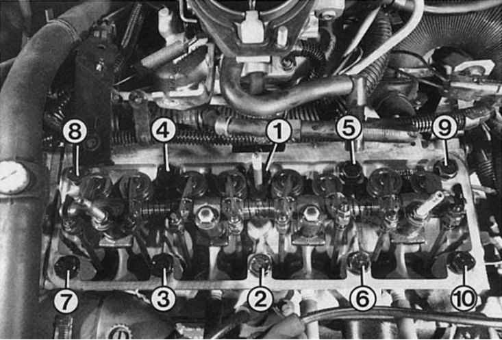
40. Remove the 10 cylinder head bolts in the opposite order to their tightening, except for bolt No. 2 (located next to the ignition distributor) from the cylinder head.
41. Move the cylinder head, rotating in a horizontal plane around the bolt number 2.
42. If the cylinder head is stuck, move it from its place with strong blows of a wooden hammer.
43. After that, unscrew the bolt No. 2 and carefully remove the cylinder head together with the intake and exhaust manifolds.
44. To protect cylinder liners from scuffing in body shops, a cylinder liner retainer is used (Mot. 521-01).
45. 16 valve engine: remove the muffler exhaust manifold heat shield from the front wall. Remove the 2 muffler exhaust manifold bolts.
46. Remove the cylinder head bolts (TORX-Stecknu in E12 and E 55 respectively) in 2 steps in reverse tightening sequence. In this case, first loosen the fastening bolts to half and only then completely unscrew them.
47. Engine type «F»: remove the cylinder head.
48. If the cylinder head is stuck, then by inserting a hardwood wedge and lightly hitting it, disconnect the block head.
49. All engines: after removal, install the cylinder head in such a way as to prevent damage to open valves.
50. Remove the old cylinder head gasket.
51. The contact surfaces of the engine housing and cylinder head must be absolutely clean. Do not damage the soft surface of the cylinder head and its gasket.
52. After cleaning the surface, remove burrs from the edges of the combustion chambers. You can use sandpaper for this. Do not damage the edges of the combustion chamber with a hard tool. The cleaned surface must not be damaged.
Note. Recommendation: when removing the block head, do not damage the sealing points of the cylinder liners.
Motor type «WITH» the pusher rods on the side of the adjusting bolts and on the side of the valve lifter must have a uniform surface. If the mating points are damaged, then the push rods must be replaced.
Checking the cylinder head
1. Check for cracks in the cylinder head on gray valves or spark plug threads.
2. Cracks with a thickness of not more than 0.5 mm or stripped initial threads of spark plugs do not affect the service life.
3. Check the cylinder head for misalignment if the engine has overheated, for which:
4. Install a hard metal ruler on the contact surface of the head of the block with the engine housing.
5. When checking with a feeler gauge, the deflection should not exceed 0.05 mm. Otherwise, the cylinder head must be replaced, as face grinding is not permitted.
Note. Recommendation: When cleaning the cylinder head, make sure that no seal residues get into the lubrication channels of the rocker axles. This also applies to the channels in the motor housing. Under no circumstances should the sealing gasket be removed with a knife or scraper, as scratches can damage the surface of the cylinder head. Renault workshops use a cleaning agent for this «Decap-joint». When using this product, the softened remnants of the gasket are removed with a wooden spatula.
Installing the cylinder head
1. The threads of the cylinder head bolts and the threads in the holes for them in the engine housing must not be damaged.
2. If the carving is damaged, then screw in new bolts of fastening of a head of the block of cylinders.
3. To prevent spinning, the motor case bolt holes must never be oil or water.
4. If the crankshaft has turned after disassembling the block head, then turn it so that none of the pistons is at TDC, otherwise the open valve may collide with the piston when installing the block head.
5. Use centering sleeves.
6. Install a new cylinder head gasket without applying sealant so that the lubrication channels are not blocked.
7. Install the block head, having previously checked whether the centering sleeves are correctly located in the engine housing, and screw in the oiled bolts by hand.
8. Tighten bolts of fastening of a head of the block of cylinders in the order specified in drawing, with the prescribed moment.
9. Engine type «WITH»: Install the push rods lubricated at both ends into the guide bushings. Replace worn push rods if necessary.
10. Establish a rocker arm axis, at the same time adjusting bolts of valves should enter directing plugs.
11. Tighten bolts of a rack of an axis of a yoke with the moment of 15—20 Nm.
12. 16 valve engine: If there are no centering sleeves, screw the two old block head bolts into the holes of the bolts No. 8 and 10 (pre-saw off the heads of these bolts and cut a slot for a screwdriver). After installing the block head, screw in the remaining 8 bolts. After that, replace the centering bolts with two new ones.
13. Engine type «F»: Establish a back casing of a gear belt.
14. Install the toothed drive belt and adjust its tension.
15. All engines: Adjust valve clearance.
16. The remaining work is carried out in exactly the same way as during dismantling, only in reverse order.
Note. Recommendation: The cylinder head bolts must only be used once.
In a diesel engine, depending on how far the pistons go, three types of gaskets are used, which have different thicknesses. To distinguish different types of gaskets, they are marked in the upper left corner, consisting of one, two or three dots. Make sure that the new cylinder head gasket has the same markings as the old one.
If the cylinder head gasket has an adhesive layer, then after removing it, you must install a new gasket.
Cylinder head tightening torques
Engine | 1.4 liter engine (C3J) | 1.7 liter engine (F3N) 1.8 liter engine (F3P) diesel (F8Q) | 16 valve engine (F7P) |
| 1. Step | Mounting bolts | Mounting bolts | Mounting bolts |
2. Step | — | No. 1-10 tighten with a torque of 70 Nm after at least 3 minutes pauses, bolts: | No. 1-10 tighten with a torque of 50 Nm |
3. Step | — | No. 1-10 completely loosen | after at least 3 minutes pause, bolts: |
4. Step | — | No. 1-10 tighten with a torque of 25 Nm | No. 1-10 completely loosen |
5. Step | — | No. 1-10 rotate further by 123 2° | No. 1-10 tighten with a torque of 20 Nm |
The tightening of the block head bolts, measured in angular degrees, must be carried out with a protractor wrench. A key without a goniometer must be equipped with a home-made cardboard scale, on which angular degrees must be applied.