
 |  |
When servicing the ignition distributor cap, limit yourself to determining wear on the contacts indicated by small arrows; state and mobility of a sliding graphite contact (arrow in the center) and scratches on the lid.
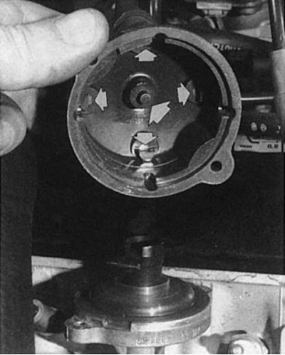 |  |
On the rotor of the ignition distributor, the arrows indicate the places to which attention should be paid if traces of soot are found. When buying a spare ignition distributor rotor, please note that if you had a glued rotor, then you need to buy the same one, and vice versa, do not confuse the ignition distributor rotor put on with a thrust ring with the glued rotor. When installing the dust cap, pay attention to its correct location in the distributor housing.
On the IEZ Renault 19 ignition system, the ignition distributor serves only to distribute the discharges produced by the ignition coil to the cylinders. At the same time, a rotor rotating in the cover of the ignition distributor supplies a high voltage electric current in accordance with the ignition order of the engine to the spark plugs.
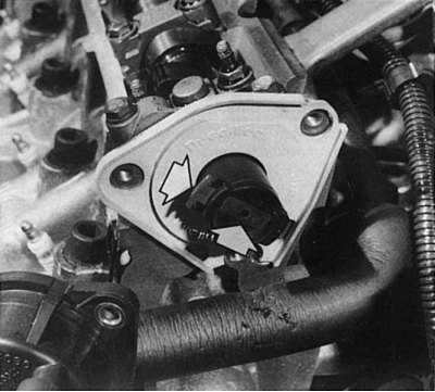
Removing the distributor cap
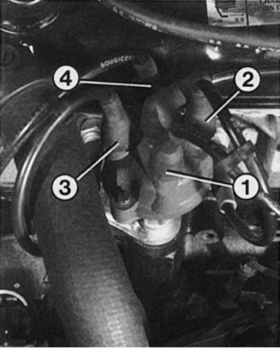
1. Loosen both TORX screws (T20) ignition distributor caps.
2. Remove the cover of the ignition distributor, while leaving the high voltage wires on.
3. Remove the ignition distributor rotor.
4. Remove the dust covers inside.
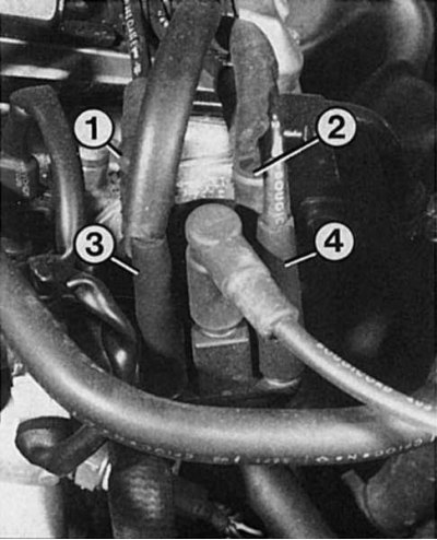
5. When installing, install the dust cover in such a way that its retaining ledge enters the recess in the edge of the ignition distributor housing.
6. The ignition distributor rotor has a welded bulge that must sit in the recess of the ignition distributor shaft.
7. The distributor cap has a anti-rotation tab that must be properly inserted into the groove before the screws are tightened.
Check of a rotor of the distributor of ignition and the distributor of ignition
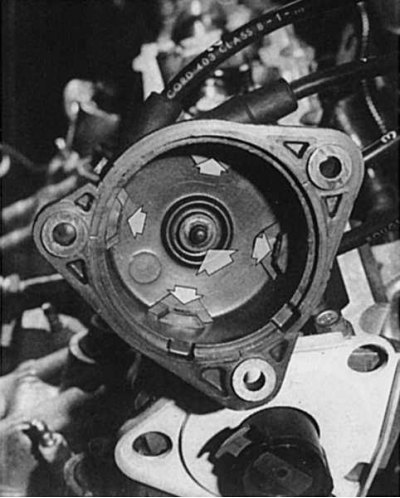
1. Remove the cover of the ignition distributor. It must be clean inside and out so that dirt or moisture does not interfere with the current flow in the ignition system.
2. Wipe off any scale on the contacts.
3. Have the contact points oxidized (copper corrosion)?
4. Strip and check up, whether the rotor of the distributor of ignition moves too far from contacts.
5. The dashes on the cover of the ignition distributor, as if drawn with a pencil, are traces of soot from the leakage current, which made its way through dirt or moisture and then burned this place.
6. As a temporary fix, you can clean these places with a screwdriver or knife and cover with all-purpose glue, nail polish, or, in extreme cases, lipstick.
7. The carbon contact in the center of the cover should be slippery and shiny, easy to press and return to its original position without jamming.
8. The contact tongue and the bulge of the central contact of the ignition distributor rotor must not be burned.
9. Finally, once again check whether the safety lug of the rotor is correctly installed in order to put it on the ignition distributor shaft.
Note. Recommendation: there are ignition distributors in which the distributor rotor is glued to the distributor shaft. In no case should this rotor be knocked off the shaft, but you should try to swing it with pliers and remove it without damage. The ignition distributor rotor must be glued after cleaning the bonding area with heat-resistant adhesive (up to 120°C).
Removing the ignition distributor
1. Disconnect the ground cable from the battery.
2. Mark position of the distributor of ignition concerning the case of the engine, having made a scratch a screw-driver.
3. Remove the mounting bolts (TORX T 40) from the cylinder head and remove the ignition distributor.
4. During installation, the ignition distributor must be installed in the same position as before disassembly.
Checking the speed sensor
1. If you think that the speed sensor is the cause of the malfunction, you first need to measure the distance between it and the flywheel.
2. To do this, insert a feeler gauge between the flywheel and the sensor. The gap should be 1.0-0.5 mm.
3. For further testing, disconnect the speed sensor connector from the ignition module.
4. Measure the resistances at both pins. It should be 200-50 ohms.
Checking the pressure sensor
As already mentioned, the control unit receives data on the pressure in the intake pipe as electrical signals from the pressure sensor.
1. To check, remove the pressure sensor hose and block it.
2. Have an assistant start the engine and let it run at medium speed (about 2000 rpm.).
3. With a steady speed, reattach the hose.
4. Since air is sucked in from the suction pipe through the hose, the ignition timing must change and, accordingly, the engine speed must increase without pressing the gas pedal.
5. If the engine does not increase speed, then either the hose is leaking or the pressure sensor is faulty.