
 |  |
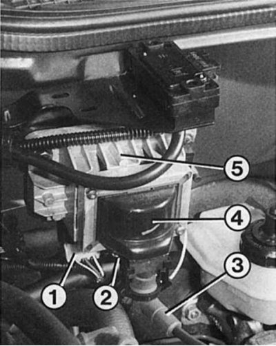
1 - contact connection of the pulse sensor; 2 - multi-pin connector for «+» (left), mass (center) and tachometer (on right); 3 - ignition module; 4 - ignition coil; 5 - high voltage wire to the cover of the ignition distributor.
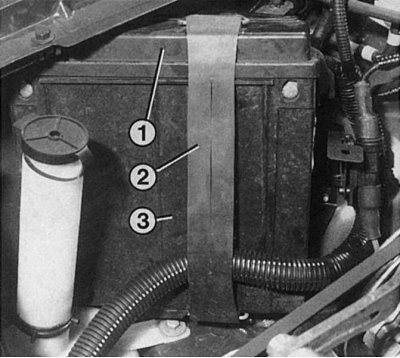
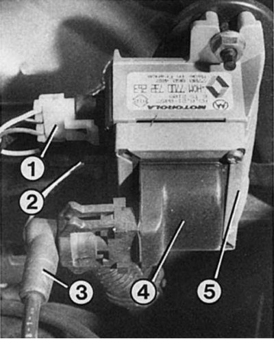
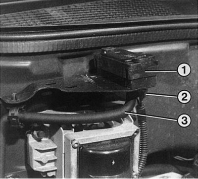
The control device is fixed in the engine compartment, in a plastic case on the right inner wing with a rubber band. To dismantle, remove the rubber band (2) and plastic body (3). Remove the cover (1) and disconnect the multi-pin connector. After loosening both screws, the control unit can be removed from the protective plastic housing. When assembling, make sure that the multi-pin connector is well and firmly inserted, since its correct installation is an indispensable condition for good ignition and fuel supply.
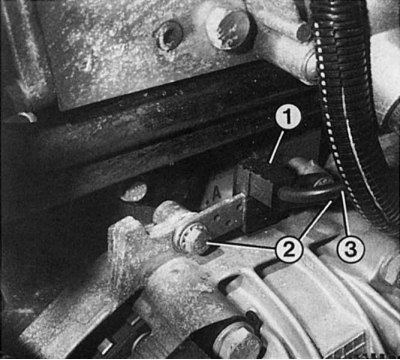
From the speed sensor (1) the control unit learns the TDC position of each piston, as well as the engine speed. The strength of the threaded fastener is very important (2) to the motor housing, as well as a reliable electrical connection (3) with ignition module. In addition, the interval between the speed sensor and the engine flywheel baffles has a certain size.
Ignition module
The ignition module and the ignition coil are combined on the Renault 19 into a single unit and are screwed to the front wall of the engine compartment. The ignition module contains a powerful transistor that turns on and off the flow of electrical current to the ignition coil. It does not, however, do so at the moment the speed sensor is transmitting a pulse. Rather, the control unit sets the correct ignition timing and at the same time gives the command to switch.
Control device
- The R19 ignition system does not require any additional device to adjust the ignition timing. All the necessary data and characteristics of the engine are stored in the memory of the control unit. They are supplied by a speed sensor, as well as a coolant temperature sensor, an intake air temperature sensor, a throttle valve potentiometer, a pressure sensor, etc. Based on the data, the control unit calculates the optimum ignition timing for a particular load condition.
- If we write the ignition timing (ignition timing), engine load condition and engine speed in a single formula, you get the so-called universal ignition characteristic. The characteristic of a modern ignition system allows you to have a precise effect on the operation of the engine in various operating modes.
- In addition, corrective programs are used for starting the engine, running a cold engine, forced idling, etc.
- The control device is always «allows» the ignition coil to use an electric current of exactly the strength that is needed at the moment. This avoids the failure of the ignition coil in extreme situations (ignition on, engine stopped) even after a long time.
- Knock control makes it possible to operate the engine with the greatest possible early ignition, which contributes to increased power.
Speed sensor
The switching on and off of the electric current supply to the ignition coil mentioned in the previous section provides (except control unit and ignition module) speed sensor, or inductive sensor. It works as follows: the sensor contains a magnet and a coil. In addition, special impulse baffles on the engine flywheel are required for the sensor to work.
Each time the baffle passes under the sensor, the magnetic field changes and voltage is applied to the coil. This small signal is sufficient for further processing in the control unit of the ignition or injection system. In this way, information about the frequency of rotation of the crankshaft is transmitted.
In order to know the exact position of the crankshaft, the sensor wheel has two wider baffles in the range of 180°. They are located 90°before top dead center of the crankshaft. Thus, the control device recognizes TDC 1 and 4 and, accordingly, 2 and 3 cylinders.
Pressure meter
Pressure meter (1) mounted in a holder on the front wall. If the ignition timing is incorrectly adjusted, the cause of the malfunction may be a damaged or improperly fitted low pressure hose (3). In this case, problems will also arise with idling due to a sharp fluctuation in engine speed. Additionally, the plug connection must be checked (2). In this case, never pull on the cable, only on the plug itself after removing the safety clip.
It is located in the ignition module holder on the front wall and is connected by a hose to the intake pipe. Through the hose, the pressure in the suction pipe influences the pressure sensitive crystal chip in the pressure sensor. Depending on the pressure in the suction pipe, the resistance value of the crystal chip changes. By changing the resistance, information about the pressure created in the intake pipe is received by the control device.
The suction pipe pressure and the actual speed are compared with each other and allow the control unit to determine the optimal engine load.
Knock sensor
Knocking combustion with too early ignition timing damages the engine. The consequences can be overheating, damage to bearings and pistons. On the other hand, early ignition provides the most engine power and is on the verge of detonation. This detonation limit depends on too many factors to be accurately determined. Therefore, all Renault 19 gasoline engines are equipped with a knock sensor that detects its presence.
The knock sensor is installed between cylinders 2 and 3 in the head of the block. This sensor has «piezoceramic» element. This material is well known from lighters in which it produces sparks to ignite the gas. Mechanical forces (thrust, pressure), which act on the piezoelectric ceramics, are converted by it into electrical voltage.
In this way, the knock sensor informs the control unit during normal combustion of information about the uniform oscillation of all 4 cylinders. As soon as the vibrations change due to detonation combustion, the control device «learns» This is done by means of a certain kind of signal from the knock sensor, upon receipt of which the ignition timing in the corresponding cylinder becomes later, until combustion again proceeds normally.