
Note. The cylinder head is removed along with the intake and exhaust manifolds.
Note. Prepare a new toothed drive belt, gaskets for the cylinder head and valve cover and (Maybe) set of new cylinder head bolts.
Removing
1. Disconnect the ground cable from the battery (contact the head Engine electrical equipment).
Attention! If the car radio in your car is coded, make sure you know the code before disconnecting the battery.
2. Drain the liquid from the cooling system, and from the cylinder block on the E7J engine, as described in Chapter Maintenance (on the E7J engine, it is important to drain the block because if wet cylinder liners are disturbed, coolant will drain into the sump).
3. Drain the engine oil as described in Chapter Maintenance.
4. Remove the toothed drive belt, refer to Section Removal, inspection and installation of a toothed drive belt from this Chapter.
5a. Remove the air filter assembly as described in Chapter Power systems, release. On the K7M engine, remove the reinforcing rod between the front suspension domes.
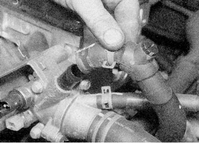
5b. Disconnect the air duct from the throttle body (refer to illustrations).
6. Disconnect the throttle cable from the throttle body (contact the head Power systems, release).
7. On the E7J engine, unscrew the accelerator cable holder from the valve cover.
8. On the K7M engine, remove the ignition coil BB from the valve cover as described in Chapter Engine electrical equipment; disconnect the high voltage wires from the spark plugs and unscrew the wire retainer from the valve cover.
9. Disconnect the crankcase ventilation hoses from the valve cover.
10. Turn away bolts and remove a valvate cover and a lining.
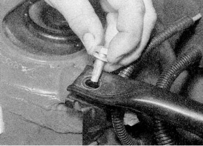
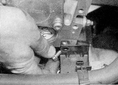
11. Unscrew the ground cable from the right side of the bulkhead (refer to accompanying illustration).
12. Loosen the clamps and disconnect the supply and return fuel hoses from the throttle body (E7J engine) or fuel line (K7M engine).
13. Disconnect the EVAP solenoid valve hose.
14. Disconnect wiring and hoses from bulkhead absolute pressure sensor. Also unscrew the wiring harness from the intake manifold, and disconnect all electrical wiring from the cylinder head (refer to accompanying illustration).
15. Loosen the bracket and disconnect the vacuum brake booster hose from the intake manifold.
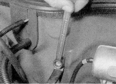
16. Turn away and remove a bolt of the top fastening of a tube of a dipstick of measurement of level of oil.
17. Remove the spark plugs as described in Chapter Maintenance.
18a. Release the clamp and disconnect the upper radiator hose from the thermostat housing. Also disconnect the heater hoses and expansion tank hose.
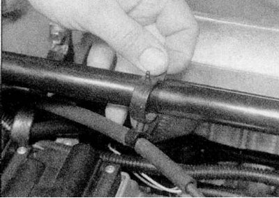
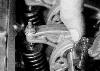
18b. Unscrew the heater hose holder on the left side of the cylinder head (refer to illustrations).
19. Turn away and remove a bolt of the top fastening/adjustment of the generator from an arm on a back part of a head of the block of cylinders.
20. Turn away nuts and remove a heat-insulating board from a final collector. Remove a reception pipe as it is described in the Head Power systems, release.
21a. Unscrew and remove the rocker shaft and mounting plate.
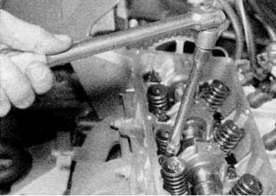
21b. Then gradually loosen the cylinder head bolts.
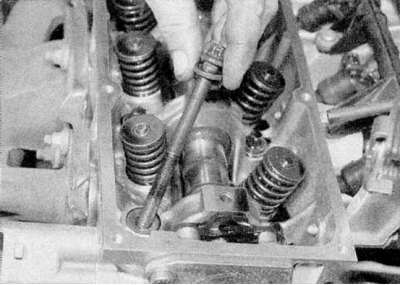
21c. Remove all bolts except for the one placed in the front right corner, which needs to be unscrewed only three or four turns.
22. Now you need to break the connection between the cylinder head, gasket and cylinder block. On the E7J engine, it is important not to lift or disturb "wet" cylinder liners.
To avoid this, pull the left end of the cylinder head forward by turning it around the retained bolt, then move the head back to its original position. If this procedure is not performed on an E7J engine, there is a possibility that the cylinder liners will move and the seals will fail, resulting in leaks after the head is installed.
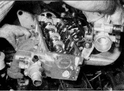
23a. Remove the remaining bolt and lift the head off the cylinder block.
23b. Then remove the gasket. Notice the mounting on the front right corner of the block (refer to illustrations).
24. Remove the inlet pipeline and a final collector as it is described in the Head Power systems, release.
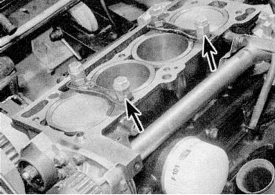
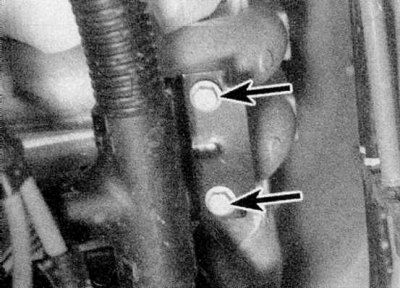
25. Please note that on the E7J engine, the crankshaft must not rotate with the head removed, as the sleeves may be displaced. If there is a need to rotate the crankshaft (e.g. when cleaning the piston crown), fix the sleeves with bolts with washers or mounting clips (refer to accompanying illustration).
Inspection
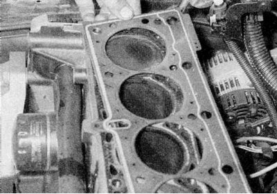
1. The mating surfaces of the head and cylinder block must be perfectly clean. Use a scraper to remove all traces of gasket and carbon deposits, and clean the tops of the pistons. Be especially careful with an aluminum cylinder head as the soft metal can be easily damaged. Also, be careful not to get dirt into the oil and water passages - this is especially important for the lubrication chain, as deposits can block the oil supply to the camshaft and crankshaft bearings and rocker arms. Using adhesive tape and paper, isolate the water, oil channels and bolt holes in the cylinder block. Clean the piston crowns in the same way.
2. Check the block and head for nicks, deep scratches, or other damage. If there are small scratches, they can be carefully removed with a file. More serious damage can be repaired by regrinding, but this work should be entrusted to a specialist.
3. Using a ruler placed on edge, check the curvature of the cylinder head. On the E7J engine, also check the protrusion of the cylinder liners. These parameters are closely related to the burnout of the cylinder head gasket.
4. Clean all bolt holes in the block. Make sure that no oil remains in them, otherwise there is a possibility that when tightening the bolts, the block may crack under the action of hydraulic pressure.
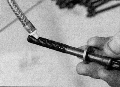
5. Examine a carving of bolts and a carving in the block of cylinders on presence of damages. If necessary, renew the threads in the block with a tap of the appropriate size and clean the threads on the bolts with a screw-cutting die. It is recommended to replace the bolts after each removal.
Installation
1. Fix the inlet pipeline and a final collector on a head of the block of cylinders, acting according to the description in the Head Power systems, release.
2. Be convinced that the piston No. 1 is placed in TDC, then wipe off the surfaces of the head and block. On the E7J engine, remove the cylinder liner clips.
3. Make sure the dowel pin is in place on the front right corner of the block.
4. Position the new gasket on the block by sliding it over the pin - the gasket can only be installed in one position (refer to accompanying illustration).
5a. Lower the head onto the block. Lubricate the threads and places under the bolt heads, install the washers.
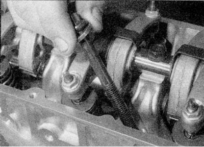
5b. Then insert the bolts. Please note that the shorter bolts are installed on the side of the intake valves - and are only screwed in by hand so far (refer to illustrations).
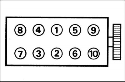
6a. Tighten the cylinder head bolts in the sequence shown in the Specifications effort (refer to illustrations).
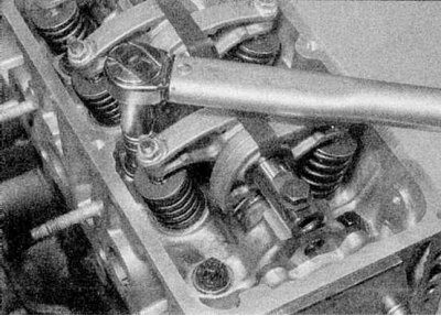
6b. When turning the bolts, mark the bolt heads and cylinder head with paint to ensure the correct angle, or purchase a special turning tool.
6c. If the bolts are tightened exactly as specified, there is no need to re-tighten them after the first start of the engine.
7. Establish an axis of yokes and a fixing plate, address to the Section Removal, inspection and installation of the camshaft. If the cylinder head has been overhauled, it is recommended at this stage to check the valve clearances to eliminate any possibility of the valves touching the pistons after the timing belt has been installed. Rotate the crankshaft so that none of the pistons is at TDC.
8. Establish a reception pipe as it is described in the Head Power systems, release, then install the heat shield on the exhaust manifold and tighten the nuts.
9. Insert a bolt of the top fastening/adjustment of the generator on a back part of a head of the block of cylinders, then adjust a drive belt tension as it is described in the Head Maintenance, and tighten the bolt.
10. Connect the expansion tank hose, heater hoses and upper radiator hose to the thermostat housing and make sure the brackets are in place.
11. Install and tighten the top bolt for the dipstick tube.
12. Connect a hose of the vacuum amplifier of a brake to the inlet pipeline.
13. Establish spark plugs as it is described in the Head Maintenance.
14. Connect electrical wiring and hoses to the absolute pressure sensor.
15. Connect the EVAP solenoid valve hose.
16. Connect the supply and return fuel hoses to the throttle body (E7J engine) or to the fuel line (K7M engine).
17. Attach the mass cable to the bulkhead.
18. Adjust valve clearances if you haven't already (refer to section Checking and adjusting valve clearances from this chapter).
19. Install the valve cover with a new gasket and tighten the bolts evenly to the Specifications effort.
20. Connect the crankcase ventilation hose to the valve cover.
21. On the K7M engine, install the ignition coil HV on the valve cover and connect the high voltage wires to the spark plugs. Attach the high voltage wire holder to the valve cover.
22. On the E7J engine, install the throttle cable bracket to the valve cover.
23. Connect a cable of a pedal of gas and adjust it as it is described in the Head Power systems, release.
24. Install the air filter assembly as described in Chapter Power systems, release. On the K7M engine, connect the air duct to the throttle body.
25. Install a new toothed drive belt, refer to Section Removal, inspection and installation of a toothed drive belt from this Chapter.
26. Fill the engine with fresh oil as described in Chapter Maintenance.
27. Install and tighten the drain plug in the cylinder block on the E7J engine.
28. Fill and bleed the cooling system as described in Chapter Maintenance.
29. Connect the mass cable to the battery.