
Note. A winch is required for this procedure. On models with aluminum tray (usually K7M engine), the engine and transmission assembly must be completely removed from the engine compartment.
E7J engine
Removing
1 Disconnect the earth cable from the battery.
Attention! If the car radio in your car is coded, make sure you know the code before disconnecting the battery.
2. Merge impellent oil, acting according to the description in the Head Maintenance, then install and tighten using a new washer.
3. Jack up the front of the vehicle and place on axle stands. Remove the right front wheel.
4. Remove the downpipe and the catalytic converter, proceeding according to the description in the Chapter Suspension and steering.
5. Disconnect a tip of cross steering draft from the lever on a rotary fist as it is described in the Head Suspension and steering.
6. Remove the top bolt securing the right suspension strut to the steering knuckle. Please note that there are grooves on the edge of the bolt head, and the bolt must be knocked out after unscrewing the nut.
7. Loosen only the lower bolt securing the strut to the steering knuckle.
8. Using a suitable drift, drive out the roll pin securing the right drive shaft to the transmission output shaft. Tilt the steering knuckle while you release the drive shaft from the slots on the output shaft. Tie the drive shaft to the steering gear.
9. Remove the bolts securing the engine to the transmission bracket/flywheel cover.
10. Remove the two nuts securing the front engine mounts to the subframe and remove the spacer from the right mount.
11. At the rear of the engine, unscrew and remove the nuts of the bolts securing the rear engine mount bracket to the transmission and the nuts of the rear mount pinch bolts. Do not remove the bolts at this stage.
12. Remove the air filter as described in Chapter Power systems, release.
13. Attach the winch to the engine using the mounting lugs. Alternatively, use a support beam located across the engine compartment.
14. Disconnect the charcoal canister hose from the solenoid valve on the intake manifold.
15. Release the supply and return fuel hoses from the inlet pipeline and frame sidewall.
16. Turn away the reservoir of a hydraulic system of the amplifier of a steering, and shift it aside. Do not disconnect hoses.
17. Disconnect the speedometer sensor from the transmission by pulling out the mounting bracket.
18. Gently lift the engine and transmission assembly so that the rear support and bracket bolts can be removed.
19. Continue to raise the assembly until it becomes possible to disconnect the hydraulic power steering pipes from the holders on the subframe.
20. Raise the assembly until the gap between the lower edge of the cylinder block and the subframe is 25 cm.
Attention! Make sure the engine/transmission assembly is securely supported before removing the sump.
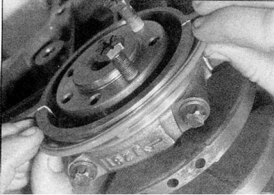
21. Remove the bolts securing the engine to the transmission bracket/flywheel cover under the sump, then remove the bolts securing the sump to the cylinder block, but leave two diagonally opposite bolts until the sump is separated from the cylinder block (refer to accompanying illustration).
22. Using a spatula, separate the pallet from the base of the cylinder block. Do not use a screwdriver as it may damage the contact surfaces.
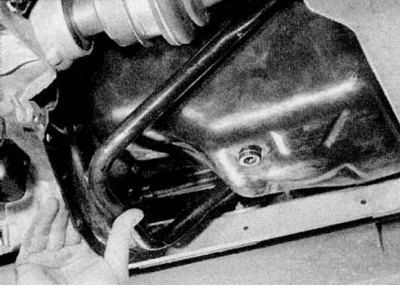
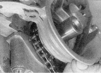
23. Turn away two remained bolts, and lower the pallet. First you need to lower it, then move it to the transmission and remove (refer to accompanying illustration).
24. Remove the rubber seals from the grooves in the right and left crankshaft main bearing caps, or from the bent portions at the ends of the sump. Clear the block of cylinders and the pallet from hermetic and wipe them dry.
Installation
1. Apply 3mm wide sealant to mating surfaces of pan, making sure to trace all bolt holes. Renault recommends Rhodorseal 5661.
2. Place new rubber seals in the grooves in the right and left crankshaft main bearing caps. Please note that the stripes are different.
3. Attach the pallet to the block of cylinders and insert bolts. Gradually tighten the bolts in a diagonal sequence to the Specifications effort.
4. Lower the engine/transmission assembly just enough to attach the power steering hydraulic pipes to the brackets on the subframe.
5. Lower assembly and install rear support bolts and bracket. Position the front mounts in the subframe and lower the assembly completely. Disconnect the winch from the engine.
6. Install the nuts on the bolts of the front and rear supports and tighten them to the Specifications effort.
7. Install the speedometer sensor on the transmission and secure it with the bracket.
8. Reinstall the power steering hydraulic reservoir and tighten the bolts.
9. Connect the fuel supply and return hoses to the intake manifold and frame side.
10. Connect the charcoal canister hose to the intake manifold.
11. Install the air filter, proceeding according to the description in Chapter Power systems, release.
12. Install and tighten engine to transmission bracket/flywheel cover bolts.
13. Fit the right drive shaft to the transmission output shaft so that the roll pin holes are properly aligned. Move the drive shaft and push the steering knuckle at the same time. Drive the outside of the roll pin into place with a suitable drift, then drive the inside. Seal both ends of the roll pin with a suitable sealant to prevent water and dirt from entering.
14. Insert the upper bolt securing the right suspension strut to the steering knuckle, then tighten the upper and lower nuts given in Specifications effort. The bolt heads must face the front of the vehicle.
15. Establish a tip of cross steering draft on the lever of a rotary fist, acting according to the description in the Head Suspension and steering.
16. Establish a reception pipe and the catalytic converter, acting according to the description in the Head Power systems, release.
17. Install the right front wheel and lower the vehicle to the ground.
18. Fill the engine with oil as described in Chapter Maintenance.
19. Connect the mass cable to the battery.
K7M engine with pressed steel sump
Removing
1 Disconnect the earth cable from the battery.
Attention! If the car radio in your car is coded, make sure you know the code before disconnecting the battery.
2. Drain the engine oil as described in Chapter Maintenance, then install and tighten the drain plug using a new washer.
3. Jack up the front of the vehicle and place on axle stands. Remove both front wheels.
4. Drain the liquid from the cooling system as described in Chapter Maintenance.
5. Loosen the clamp and disconnect the upper radiator hose from the thermostat housing.
6. Remove brackets and mounting screws and remove the right front wheel arch liners
7. Disconnect the oxygen sensor wiring, then remove the catalytic converter and the front exhaust pipe of the muffler / converter as described in Chapter Power systems, release.
8. Mark the position of the main selector rod on the front fork in the transmission, then loosen the pinch bolt and separate the two parts of the rod.
9. Disconnect a tip of cross steering draft from the lever of the left rotary fist as it is described in the Head Suspension and steering.
10. Remove the three bolts securing the left drive shaft inner boot to the transmission.
11. Remove both bolts securing the left suspension strut to the steering knuckle. Please note that there are grooves on the edge of the bolt head, and the bolt must be knocked out after unscrewing the nut.
12. Carefully separate the left drive shaft inner joint from the transmission. Tie up the drive shaft to the side.
13. Remove the top bolt securing the right suspension strut to the steering knuckle. Please note that there are grooves on the bolt head, and after removing the nut, the bolt must be knocked out.
14. Relax (don't shoot) the lower bolt that secures the strut to the steering knuckle.
15. Using a suitable drift, drive out the roll pin securing the right drive shaft to the transmission output shaft. Tilt the steering knuckle while you release the drive shaft from the slots on the output shaft. Tie the drive shaft to the steering gear.
16. Turn away bolts of fastening of the engine to an arm of transmission/a flywheel cover.
17. On the front side of the subframe, remove the nuts from the front engine mounts and remove the plate from the right mount.
18. At the rear of the engine, loosen and remove the nuts from the bolts securing the rear engine mount bracket to the transmission and the rear mount pinch bolt nuts. Do not remove the bolts at this stage.
19. Turn away bolts and remove a reinforcing core between domes of a rack of a forward suspension bracket.
20. Turn away a cable of weight from the right side of a bulkhead.
21. Remove the spring clip and remove the speedometer sensor from the rear of the transmission.
22. Remove the bolts or separate the power steering reservoir from the engine and place it on the engine. Disconnect the vacuum brake booster hose from the intake manifold.
23. Disconnect the charcoal adsorber hose from the intake manifold.
24. Where necessary, disconnect the crankcase ventilation hose.
25. Disconnect wiring from throttle potentiometer.
26. Disconnect the supply and return fuel hoses from the fuel pressure regulator and fuel line. Contact the Head Power systems, release, if it is needed.
27. Attach winch to engine/transmission assembly and lift engine slightly.
28. Where applicable, release the clutch cable in the engine compartment.
29. Gently lift the engine and transmission assembly just enough to remove the rear support and bracket bolts.
30. Continue to raise the assembly until it becomes possible to release the hydraulic power steering tubes from the holders on the subframe.
31. Raise the assembly until there is a 26 cm gap between the lower edge of the cylinder block and the subframe. Make sure that the engine wiring is not pinched between the transmission and the side of the frame.
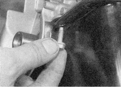
32. Remove the bolts securing the sump to the cylinder block, but leave two diagonally opposite bolts until the sump is separated (refer to accompanying illustration).
33. Using a spatula, separate the pallet from the base of the cylinder block. Do not use a screwdriver as it may damage the contact surfaces.
34. Turn away two remained bolts and lower the pallet. First you need to lower it, then move it to the transmission and remove (refer to accompanying illustration).
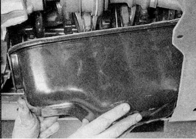
35. Remove the rubber seals from the grooves in the left main bearing caps.
36. Remove the rubber seals from the grooves in the right crankshaft main bearing caps or from the bent portions at the ends of the sump. Clean the cylinder block and sump from the sealant and wipe them dry (refer to illustrations).
Installation
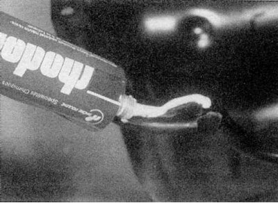
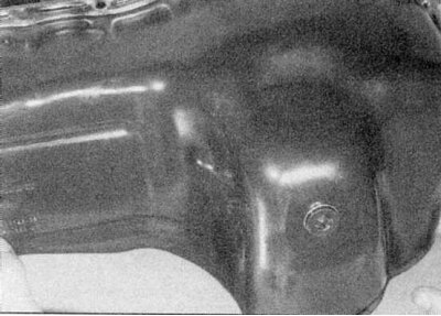
1. Apply 3mm wide sealant to mating surfaces of pan, making sure to trace all bolt holes. Renault recommends Rhodorseal 5661 (see illustration).
2. Place new rubber seals in the grooves in the right and left crankshaft main bearing caps. Please note that the stripes are different.
3. Attach the pallet to the block of cylinders and insert bolts. Gradually tighten the bolts in a diagonal sequence to the Specifications effort.
4. Lower the engine/transmission assembly just enough to attach the power steering hydraulic pipes to the brackets on the subframe.
5. Lower assembly and install rear support bolts and bracket. Position the front mounts in the subframe and lower the assembly completely. Disconnect the winch from the engine.
6. Install the nuts on the bolts of the front and rear supports and tighten them to the Specifications effort.
7. Where necessary, secure the clutch cable in the engine compartment.
8. Connect the supply and return fuel hoses to the fuel pressure regulator and fuel line and tighten the brackets.
9. Connect the wiring to the throttle potentiometer.
10. Connect the crankcase ventilation hose.
11. Connect the charcoal adsorber hose and brake booster hose to the intake manifold and tighten the clamps.
12. Establish a bull of a hydraulic system of the amplifier of a steering and tighten bolts.
13. Install the speedometer sensor on the transmission and secure it with the bracket.
14. Attach the ground cable to the right side of the bulkhead.
15. Install the reinforcing rod on the strut domes and tighten the bolts.
16. Install the nuts on the bolts of the front and rear supports and tighten them with the tightening torque regulated specifications.
17. Install and tighten engine to transmission bracket/flywheel cover bolts.
18. Fit the right drive shaft to the transmission output shaft so that the roll pin holes are properly aligned. Move the drive shaft and push the steering knuckle at the same time. Drive the outside of the roll pin into place with a suitable drift, then drive the inside. Seal both ends of the roll pin with a suitable sealant to prevent water and dirt from entering.
19. Insert the upper bolt securing the right suspension strut to the steering knuckle, then tighten the upper and lower nuts given in Specifications effort. The bolt heads must face the front of the vehicle.
20. Attach the left drive shaft inner joint to the transmission, then install the bolts securing the left suspension strut to the steering knuckle. The bolt heads must face the front of the vehicle. Tighten the nuts given in Specifications effort.
21. Install the three bolts securing the left drive shaft inner boot to the transmission and tighten to Specifications effort.
22. Establish a tip of cross steering draft on the lever of a rotary fist, acting according to the description in the Head Suspension and steering.
23. Install the main selector rod on the front fork in the transmission, then tighten the pinch bolt to Specifications effort.
24. Establish the catalytic converter and a reception pipe as it is described in the Head Power systems, release and connect the oxygen sensor wiring.
25. Establish liners of an arch of the right forward wheel.
26. Connect the top hose to the thermostat housing.
27. Install the front wheels and lower the vehicle to the ground.
28. Connect the mass cable to the battery.
29. Fill the engine with oil (contact the head Maintenance).
30.Fill the cooling system (contact the head Maintenance).
K7M engine with aluminum sump
Removing
1. Remove the engine and transmission assembly from the vehicle.
2. Turn away the bolts fastening the pallet to a side of cylinders and separate the pallet from the basis of the block of cylinders. Do not use a screwdriver as this may damage the contact surfaces.
3. Remove the sump, then remove the rubber seals from the grooves in the right and left crankshaft main bearing caps, or from the bent portions at each end of the sump. Clear the block of cylinders and the pallet from hermetic and wipe them dry.
Installation
1. Apply 3mm wide sealant to mating surfaces of pan, making sure to trace all bolt holes. Renault recommends Rhodorseal 5661.
2. Place new rubber seals in the grooves in the right and left crankshaft main bearing caps. Please note that the stripes are different.
3. Attach the pallet to the block of cylinders and insert bolts. Gradually tighten the bolts in a diagonal sequence to the Specifications effort.
4. Install the engine/transmission assembly into the vehicle.