
Withdrawal order:
- disconnect the wire from the negative terminal of the battery;
- remove the hood;
- support the engine pan with a jack, placing a wooden spacer between them;
- remove the camshaft drive belt as described below;
- remove the protective casing of the engine tray and drain the coolant from the engine, as described in subsection «Cooling system»;
- drain the engine oil as described in subsection «Maintenance»;
- remove the throttle cable from the cylinder head;
- dismantle the protective casing of the fuel distribution rail;
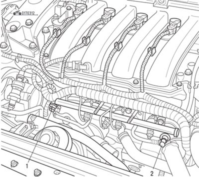
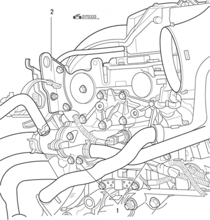
Pic. 3.12. Disconnecting pipelines from the fuel distribution rail: 1 - supply pipeline; 2 - return pipeline
- disconnect the pipelines from the fuel distribution rail (pic. 3.12) and take them aside;
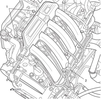
Pic. 3.13. Removing the air filter mount (1) and contact connector (2) at the front of the engine
- disconnect the electrical wires suitable for it from the cylinder head by disconnecting the corresponding connectors (pic. 3.13);
- remove the air filter housing, for which disconnect and set aside the expansion tank of the engine cooling system;
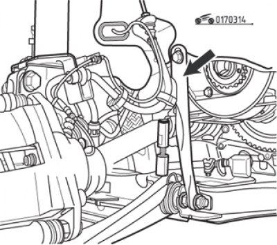
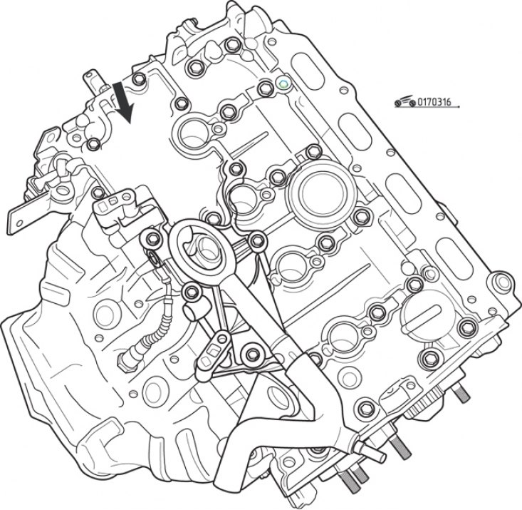
Pic. 3.14. Engine Support Brace (arrow)
- remove the tie rod supporting the engine on the right side of the exhaust manifold (pic. 3.14);
- remove the fastening parts of the converter, separate it from the exhaust manifold and fix the converter on the pipeline of the exhaust gas system;
- remove the throttle body;
- remove the connector of the oxygen concentration sensor;
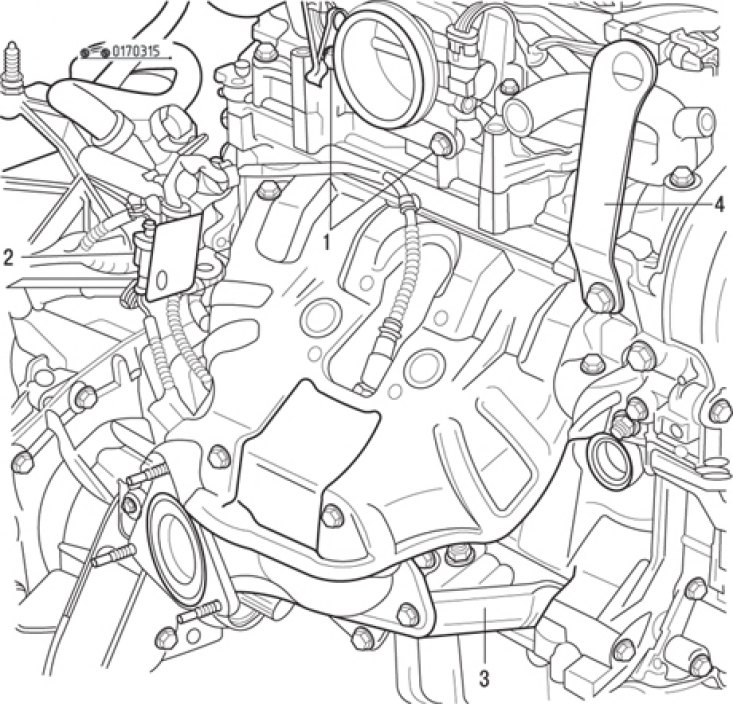
Pic. 3.15. bolts (1) throttle body mounts, connector (2) exhaust gas oxygen concentration sensor, strut (3) engine mounts and lifting eye (4)
- remove the strut and lifting eye (pic. 3.15);
- remove the exhaust manifold by disconnecting the vacuum hose from it;
- remove the ignition coils from the spark plugs (see subsection «Ignition system»);
Pic. 3.16. Oil separator on the cylinder head cover (arrow)
- remove the oil separator from the top of the cylinder head cover (pic. 3.16);
Pic. 3.17. Removing the cylinder head cover: 1 - eyes; 2 - points for bringing a screwdriver used as a lever
- unscrew the bolts securing the cylinder head cover, gradually loosening them, then separate the cover in a vertical direction, hitting the lugs at points 1 (pic. 3.17) with a bronze drift and using a screwdriver as a lever at points 2 (wrap the screwdriver so as not to damage the aluminum surfaces);
- remove the camshafts from the cylinder head. The intake shaft is marked «AM», high school graduation - «EAT». If there is no marking, mark the shafts with paint;
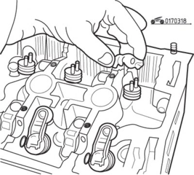
Pic. 3.18. Removing the roller rocker arms from the cylinder head
- remove and place in order in separate plastic cups (drawers, boxes) roller rocker arms so as not to confuse them during installation (pic. 3.18);
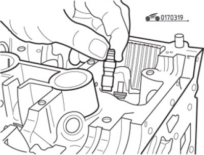
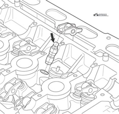
Pic. 3.19. Removing hydraulic pushers
- take a metal box with 16 compartments and fill it with clean engine oil. Carefully, in order, remove the hydraulic pushers from the sockets (pic. 3.19) and arrange them in compartments, completely immersed in oil;
- remove the hoses on the thermostat unit located on the coolant outlet pipe from the cylinder head and the coolant temperature sensor connector;
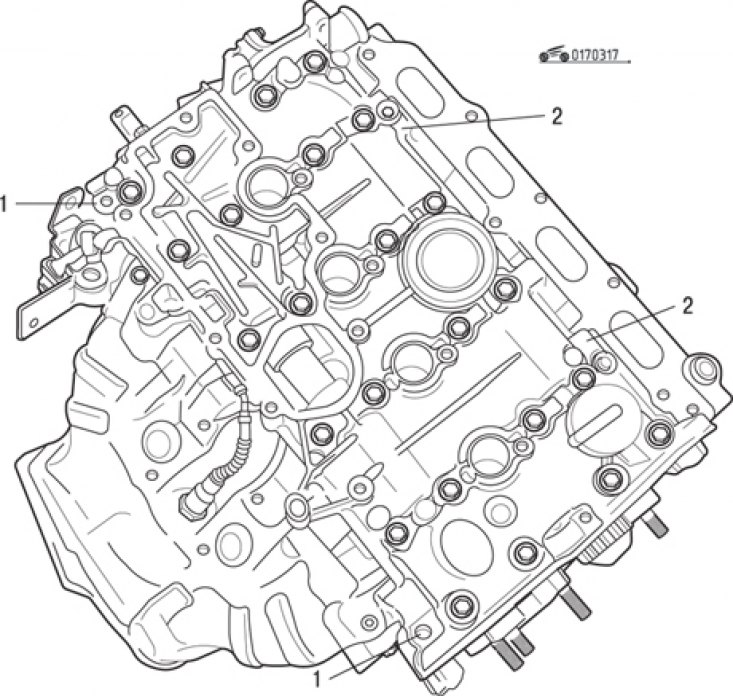
Pic. 3.20. Head Mount Holder (1) wiring harness and lifting eye (2)
- remove the fasteners of the harness holder at points 1 (pic. 3.20) and lifting eye 2;
- turn out the spark plugs;
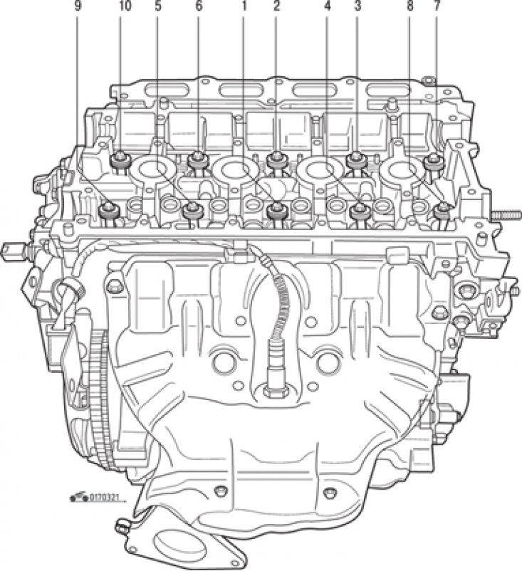
Pic. 3.21. Cylinder head bolt tightening sequence
- gradually loosening, turn away bolts of fastening of a head of the block of cylinders in an order, the return specified in fig. 3.21;
- carefully with an assistant, remove the head from the cylinder block together with the gasket.
Before installing the cylinder head, carry out the following operations.
Cleaning
It is strictly forbidden to clean the mating surfaces of aluminum parts with a tool with a sharp edge.
Use Decapjoint, which dissolves the remnants of the gasket.
Apply the indicated agent to the surface to be cleaned, wait approximately 10 minutes, then remove the agent with a wooden spatula. Perform this operation with protective gloves. When performing this operation, take special precautions to prevent the entry of foreign particles into the channels for supplying pressurized oil to the rocker shafts (these channels are made in the cylinder block and in the block head).
Checking the mating surface
Using a straightedge and a set of feeler gauges, check the deformation of the mating surface. The maximum allowable flatness is 0.05 mm. Grinding of the cylinder head is not allowed. Check the cylinder head for possible cracks. Check the condition of the cylinder head bolts: the bolts can be reused if the length of the bolt shaft under the head does not exceed 117.7 mm. Otherwise, replace all bolts. For the correct tightening of the bolts, use a syringe to remove the oil remaining in the mounting holes of the cylinder head for the mounting bolts. Do not lubricate new bolts with engine oil. On the other hand, reused bolts must always be lubricated with engine oil.
Installation order:
- turn the crankshaft pulley bolt clockwise with a wrench or head so that the pistons are approximately in the middle of their stroke to prevent valve failure;
- lay a new gasket on the cylinder block;
- if the lower part of the intake manifold was removed, it must be installed at this stage before tightening the mounting bolts, making sure that the side facing the valve timing mechanism is installed flush with the side of the cylinder head;
- carefully lower the head onto the cylinder block without displacing the gasket;
- insert checked (or replaced) bolts and tighten them by hand;
- tighten bolts of fastening of a head of the block of cylinders the moment of 20 Н·м in the order specified in fig. 3.21, then tighten all the bolts in the same order by 240°±6°. After this procedure, no further tightening of the bolts is required. In the absence of a goniometric nozzle on the crank, pre-apply with paint an angular marking on the cylinder head;
Pic. 3.22. Checking the hydraulic pusher (force is applied in the direction of the arrow)
- check hydraulic pushers (pic. 3.22), by pressing your finger on their end in the direction of the arrow indicated in the figure. If the plunger sinks, then the hydraulic pusher needs to be pumped. To do this, completely immerse the hydraulic pusher in a container with engine oil and press its end several times;
- remove the hydraulic pushers from the cells of the oil box and install each in its place;
- one by one, remove the roller rocker arms from the boxes and put them in their places;
- lubricate the camshaft bearings. Do not allow oil to get on the mating surface of the cylinder head cover;
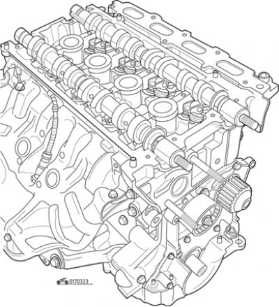
Pic. 3.23. Installation of camshafts (toothed sprockets removed)
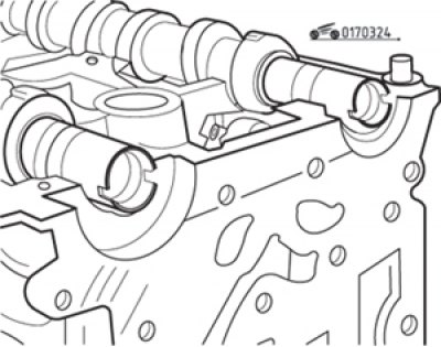
Pic. 3.24. The location of the grooves on the ends of the camshafts (flywheel side view)
- put the camshafts on the marked marks in their places (pic. 3.23). Grooves at the ends of the shafts (flywheel side) must be horizontal (pic. 3.24);
- set the piston of the first cylinder to the TDC of the compression stroke, as described below in the subsection «Removing, installing and adjusting the timing belt tension»;
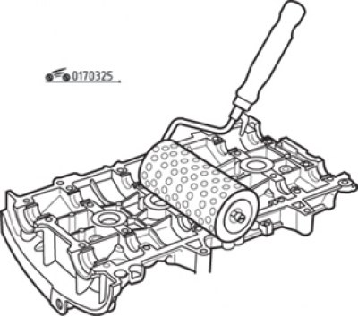
Pic. 3.25. Roller application of sealant to the surface of the cylinder head cover
- make sure the mating surfaces of the head and cover are clean. They must be clean, dry and free of grease (especially avoid touching them with your fingers, so as not to leave traces of fat). Using a roller, apply Loctite 518 to the surface of the cylinder head cover until it turns reddish (pic. 3.25);
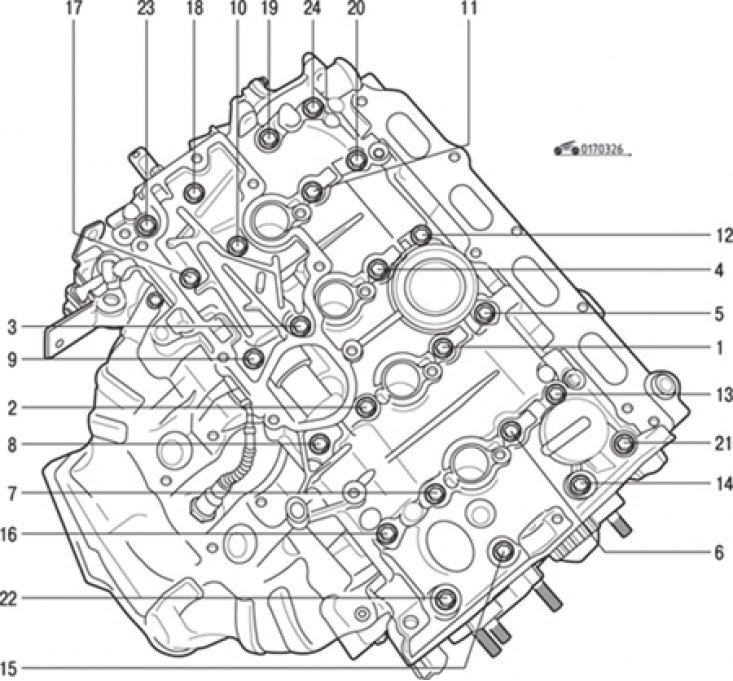
Pic. 3.26. Cylinder head cover bolt tightening sequence
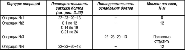
- Establish a cover of a head of the block of cylinders and tighten bolts of its fastening in the sequence specified in fig. 3.26. The tightening torques are given in table. 3.1;
Table 3.1. Torques and tightening sequence for cylinder head cover bolts
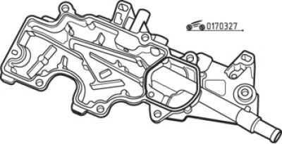
Pic. 3.27. The mating surface of the oil separator, on which the sealant is applied
- make sure the mating surfaces of the oil separator and cylinder head are clean. They must be clean, dry and free of grease (especially avoid touching them with your fingers, so as not to leave traces of fat). Apply Loctite 518 to the surface of the oil separator with a roller until it turns reddish (pic. 3.27);
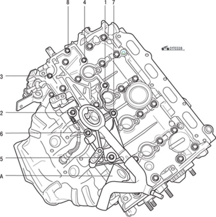
Pic. 3.28. The sequence of tightening the oil separator mounting bolts: A - lifting eye
- install the oil separator, tightening its fastening bolts to the specified torque, and the lifting eye (pic. 3.28);
- perform the remaining operations in the reverse order of removal;
- fill the engine with oil and coolant, start the engine, make sure it runs normally and there are no oil and fluid leaks.